Assembly – RIKON Power Tools 25-010 User Manual
Page 6
6
CAUTION! To install the legs the
machine must be placed onto its side.
The machine is heavy. Additional help
or a suitable lifting device or support
will be required for lifting the machine
onto the stand.
Note: With the machine laying on
its side, it is easier to gain access to
the underside to secure the nuts and
washers.
Note: When assembling this Planer/
Jointer, DO NOT fully tighten the
nuts and bolts until the assembly is
complete.
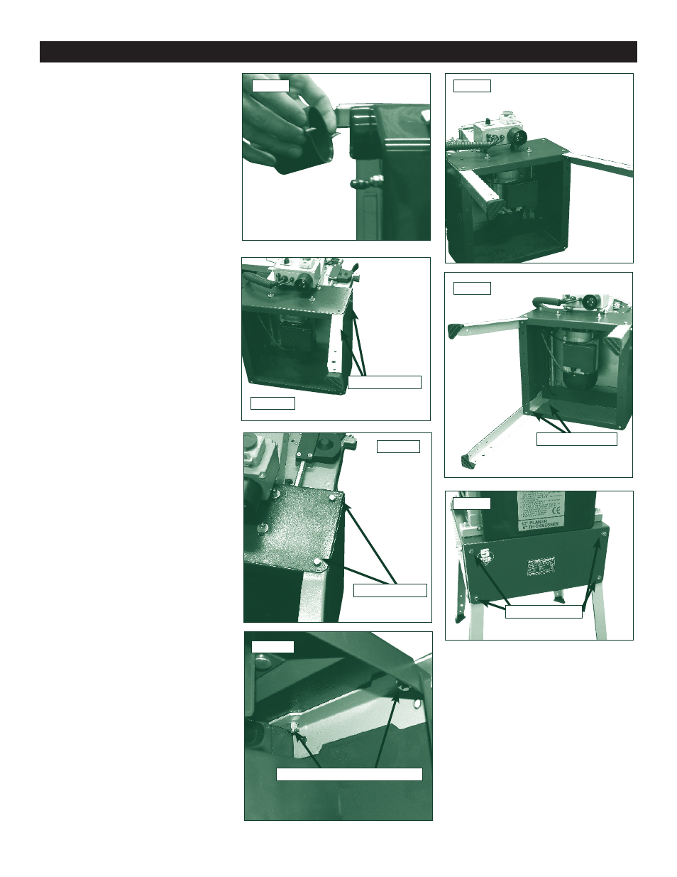
3.2 Stand Assembly
1. Before laying the machine down
on its side, remove the spindle cover
from the back of the machine Fig.3.2.
Preferably though; if the switch has
not yet been installed then lay the
machine down on this side, as this is
steel panelling with no obstructions.
2. Gently lay the machine onto it's
side. Ensuring that the weight of the
machine is distributed equally across
the main frame.
Note: The waste packaging may be
utilised to support the machine on its
side, preventing damage especially if
the machine is laid on the side which
has a plastic cover.
3. With the machine on its side, locate
the first leg and secure it to the main
frame of the machine, using the nuts,
bolts and washers provided Fig.3.3A,
Fig.3.3B and Fig.3.3C.
4. In the same way, attach the second
leg to the main frame Fig.3.4.
5. Continue the same process until
legs three and four have been se-
cured to the main frame Fig.3.5. How-
ever, it may not be possible to fix the
lower fixing bolts until the machine is
in the upright position.
6. With assistance or a suitable lift-
ing device, return the machine to an
upright position, ensuring that all four
legs are stable, secure and on a level
footing Fig.3.6. Fit the final four bolts.
CAUTION! Do not attempt to lift the
machine single handed. Seek assist-
ance or use a suitable lifting device.
Fig.3.3A
Fig.3.3B
Fig.3.3C
Fig.3.4
Fig.3.2
Fig.3.5
FIXING BOLTS
FIXING HOLES
FIXING NUTS AND WASHERS
Fig.3.6
LOWER BOLTS
FIXING BOLTS
Assembly