Maintenance – RIKON Power Tools 25-010 User Manual
Page 16
16
Maintenance
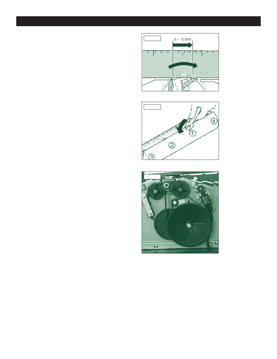
Fig.6.6
B: By using an aluminium straight edge Fig.6.6.
1. Place the aluminium straight edge as shown over
the outfeed table and cutterhead.
2. Turn the cutterblock by hand, one turn against the
direction of feed.
The planer knives are set correctly if the straight
edge is moved forward 4 to 6mm by turning the cut-
terhead. This check must be performed at both ends
of the cutterhead.
Fig.6.7
Fig.6.8
5. To set the knife projection, turn the grub screws in the
planer knife lockbar with a 3mm Allen key as required.
6. To tighten, turn the four screws of the planer knife
lockbar fully out. To prevent distortion of the planer knife
lockbar start with the screws in the centre, moving out to
the edges Fig.8.7.
7. Return the cutterblock guard extrusion to its starting
position.
8. Mount the jointer fence.
Belt Tension
After the first 5 hrs. of operation check belt tension. Re-
move cap securing the belt drive cover (pt. No.215). Check
tension by pushing against belt, play should be approxi-
mately 15 – 20 mm or 5/8” – 3/4”. (see Fig.15) Belt tension
is adjusted by slackening the four nuts A using the 13mm
wrench provided, correctly tension, then re-tighten nuts
Fig.8.8.