Assembly instructions 5x10x8 cyclecabana – Rhino Shelter SHED-5WX10LX8H User Manual
Page 5
Assembly Instructions
5x10x8 CycleCabana
TM
V1.0
Do NOT Return Assembly To Dealer or Store. For All Questions or Shortages Please Call MDM Products Directly
Customer Service 800-447-7079 or 203-877-7070
4
Swedged end of the Cross Rails should face the interior of
the unit to accept the next Cross Rail. The Cross Rails
should be put into the bottom and side hole of the arch
upright. Again, don't tighten the hardware until the next
arch and cross rails are assembled. It is very important to
make certain all nuts are on the inside of the unit to avoid
damaging the cover when put on.
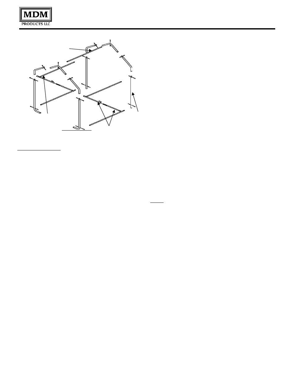
Part #5 Top
Ridge Rail
Stand the interior arch assembly up vertically into position,
so the cross rails align with the holes in the interior arch.
Using four(4) Carriage Bolts #CBN-3000-3 (Part #9) with
nuts and washers, connect the cross rails between the end
arch and the first interior arch assemblies. Connect the
two(2) Wind Braces (#7 & #8) diagonally across the end
and interior arch as shown in Figure 3
Figure 3
Frame Assembly
Step1. Assemble the Front and Rear End Arches(2)
using (1) Top Crest (Part #2), (2) Bent Tube Side Crest
(Part #1) and (2) End Upright w/Foot (Part #3) for each
one. Use (4) #CBN-3005-2 carriage bolts (Part #10)
with nuts and washers through pre-drilled holes in frame
members.
Be certain to insert carriage bolts from the outer edge
into the interior of the unit, with the washers and nuts on
the inside of the arches. This will avoid tearing the fabric
on doors and main cover when installed. Do not tighten
the nuts completely until the frame is completed and set
in place.
Step 2. Assemble the (2) Corner Wind Braces (Parts #7
& #8) to the End Upright w/Foot (#3) to the first of the
End Arch assemblies. Use a #CBN-3005-3 Carriage Bolt
(Part #9) with Washer and Nut to secure the braces
loosely to the Upright. Do not tighten completely.
Step 3. Assemble the remaining two interior arches
using (1) Top Crest Tube (#2), (2) Bent Tube Side Crest
(#1), and (2) Center Straight Upright (Part #4) for each of
the arches. Use CBN-3000-2 carriage bolts (#10) with
washers and nuts in the pre-drilled holes, aligned to form
the arch.
Step 5 Begin the Top Ridge Rail (#5) by placing a Top
Crest Tube (#2) underneath the End Top Crest Tube.
Secure the Cross Rail loosely with a Carriage Bolt #CBN-
3000-2 (#10) with washer and nut facing the interior of the
unit.
Step 6 Add rear end arch in the same fashion. Note that
the plain end of the Swedged Cross Rail should fasten
under the End Top Crest Arch and the Swedged End
above middle Top Crest Arch.
NOTE: Do not completely tighten bolts that connect the
Cross Rails to the End Arches. They must be removed for
proper for End Panel Zippered Door installation
Step 7. Move the frame assembly into its final installation
location. This should be done with at least one person
lifting each side or corner to avoid bending or stressing any
frame members. Frame should now be squared up in
position. Measure from diagonally from inside corner to
inside corner. Adjust frame and support as necessary to
bring frame into square. Failure to square frame of unit
will result in poor cover fit and reduced strength and
rigidity. If end or interior upright
ends are placed on soft material that will not support
weight, recess small patio blocks or bricks under leg ends.
This will also allow better setting of frame before securing
to ground.
Step 4. Support the End Arch with Wind Braces
temporarily in the vertical position. Connect (5) (Part #5)
Swedged Cross Rails to the End Arch with (4) CBN-
3005-3 carriage bolts (Part #9), washers, and nuts
through the pre-drilled holes in the arch members.
TheSwedged end of the Cross Rails should face the
interior of the unit to accept the next cross rail. The
Step 8. Once frame is square and properly supported,
tighten carriage bolts on all frame members, except for End
Arch members to Cross Rails along base, side, and top.
After hardware is tightened, insert plastic end plugs (Part
#16) (1 5/8”) & (Part #15) (1”) into all open ends of frame
members.
Part #4
Center
Straight
Upright
Part #6 Cross
Rail B
Part #7 & #8
Corner Wind
Brace