Site preparation, Frame arch assembly, Combine end arch & interior arch – Rhino Shelter BARN-12W X 28L X 12H User Manual
Page 3: Assembly instructions
Assembly Instructions
Barn Style 12 x 28 x 12
V1.2
Do NOT Return Assembly To Dealer or Store. For All Assembly Questions or Shortages Please Call MDM Products Directly
Customer Service 800-447-7079 or 203-877-7070
3
SITE PREPARATION
Select a level or as close to level as practical location for
your Rhino Shelter unit. The unit should be placed on a
base of materials suitable for the storage load to be
protected. A bed of crushed process rock will make an
ideal base. The unit should not be located under trees,
which will shed hard fruit such as apples, walnuts, or
heavy pine cones. The cover of your unit will protect
against normally leaves and light debris, however large
branches or other falling items may cause puncture or
tears in the cover material.
Take notice of drainage both near and around your
intended location. Water draining from the surrounding
terrain should be planned so that it does not run into the
unit. As well, rain or melting snow that comes off the
unit should be drained away rather than accumulate and
pool around the unit.
Check to be certain that adequate clearance is allowed
for entry and exit from ends of unit. As unit has doors on
both ends, ideally vehicle or contents can be inserted or
removed from either end.
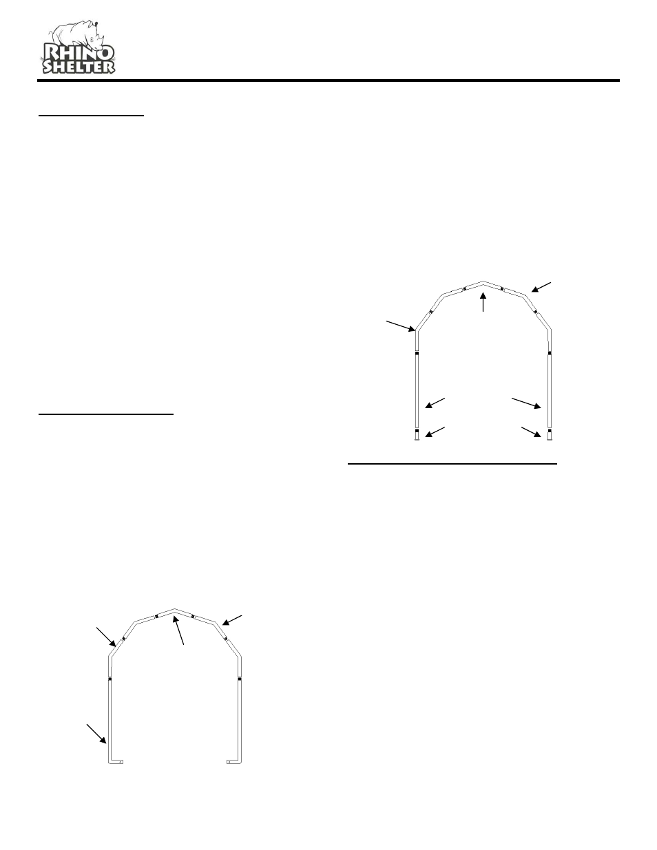
FRAME ARCH ASSEMBLY
Step1. Assemble the (2) Front and Rear End Arches
using (1) #3 Top Crest Tube, (2) #1 Top Crest Support
A, (2) #2 Top Crest Support B, and (2) #8 End Upright
with Foot for each arch. Use (4) 4” carriage bolts with
nuts and cupped washers through pre-drilled holes in
frame members.
Be certain to insert carriage bolts from the outer edge
into the interior of the unit, with the washers and nuts on
the inside of the arches. This will avoid tearing the fabric
on doors and main cover when installed. Do not tighten
the nuts completely until the frame is completed and set
in place.
Step 2. Assemble the (2) Corner Wind Braces #9 to #8
End Upright w/Foot to the first of the End Arch
assemblies. Use a #13 4”Bolt with Washer and Nut to
secure the braces loosely to the Upright. Do not tighten
completely.
Step 3. Assemble the remaining four interior arches
using (1) #3 Top Crest Tube, (2) #1 Top Crest Support
A, (2) #2 Top Crest support B, (2) #7 Straight Upright,
and (2) #6 Foot Plate Tubes for each of the arches. Use
#13 4” carriage bolts with washers and nuts in the pre-
drilled holes, aligned to form the arch.
#2 Top Crest
Support B
COMBINE END ARCH & INTERIOR ARCH
Support the End Arch with Wind Braces temporarily in
the vertical position. Connect (4) #4 Swedged Cross
Rails to the first End Arch with (4) 3” Carriage bolts,
washers, and nuts through the pre-drilled holes in the
arch members. The Swedged end of the Cross Rails
should face the interior of the unit to accept the next
cross rail. The Cross Rails should be put into the bottom
and side hole of the arch upright. Again, don’t tighten
the hardware until the next arch and cross rails are
assembled. It is very important to make certain all nuts
are on the inside of the unit to avoid damaging the cover
when put on.
#8 Upright
with Foot
#1 Top Crest
Support A
#2 Top Crest
Support B
#3 Top Crest
Tube
#6 Steel Foot
#7 Straight Upright
#3 Top Crest
Tube
#1 Top Crest
Support A