3 connecting additional analyzing devices, 3 mechanical installation, 1 fiber optic – LumaSense Technologies IGA 320/23-LO User Manual
Page 15
IGA 320/23-LO Operating Manual
Controls and Connections 15
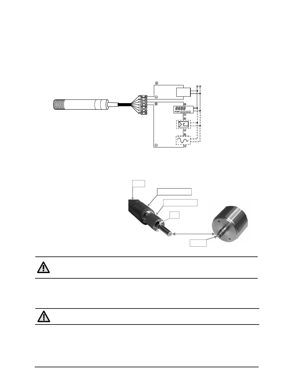
3.2.3 Connecting additional analyzing devices
Additional analyzing instruments, such as a LED digital display instrument, need to be connected
to a power supply and the analog outputs from the pyrometer. Other instruments, like a
controller or printer, can be connected to the display in series as shown below (total load of
resistance max. 500 Ohm).
3.3 Mechanical Installation
3.3.1 Fiber optic
The fiber has either a blue mark
(MB 7) or a red mark (MB 12) for
correct connection to the pyrometer.
This color mark has to be mounted on
the pyrometer’s side.
Please note that the connector on the
instrument side of the fiber has an
alignment pin. When connecting to
the socket, you have to turn the
connector until the pin is in the right
orientation before you can fix the
connector with the knurled nut.
Fiber
Screw connection
Pin
Cut-out
Blue or Red mark
Attention: The light guide end of the fiber optic cable as well as the
socket/connector and the optical head must always be protected with the caps when
not connected!
Ambient temperature
The fiber and optical head can withstand ambient temperatures up to 200 °C without cooling on
the side of the optical head.
Attention: The temperature of the fiber and optical head must be at least 30 °C
lower than the measuring temperature to get a correct temperature reading.
Serial number
The original fiber has a serial number which is also on the pyrometer’s housing. If required, the
fiber can be replaced by a new original IMPAC-brand fiber. In this case, the pyrometer has to be
calibrated together with the fiber (service).
yellow
LED digital display
Controller
Power supply
green
brown
white
230V ~
24 V DC
°C
Writer