Installation, Warning, Caution – Lincoln Electric IM813 RANGER 305 D (CE) User Manual
Page 17
A-5
INSTALLATION
RANGER 305D (CE)
A-5
WELDING TERMINALS
The machine is equipped with a toggle switch for
selecting "hot" welding terminal when in the "WELD
TERMINALS ON" position or "cold" welding terminal
when in the "REMOTE" position.
WELDING OUTPUT CABLES
With the engine off connect the electrode and work
cables to the output studs. The welding process dic-
tates the polarity of the electrode cable. These con-
nections should be checked periodically and tightened
with a 19mm wrench.
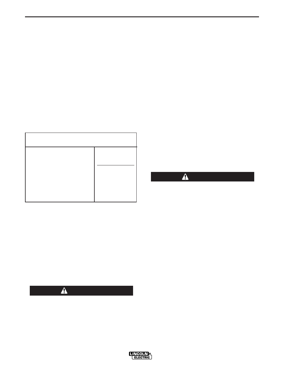
Table A.1 lists recommended cable sizes and lengths
for rated current and duty cycle. Length refers to the
distance from the welder to the work and back to the
welder. Cable diameters are increased for long cable
lengths to reduce voltage drops.
TABLE A-1
CABLE INSTALLATION
Install the welding cables to your machine as follows:
1. The diesel engine must be OFF to install welding
cables.
2. Remove the flanged nuts from the output terminals.
3. Connect the electrode holder and work cables to
the weld output terminals. The terminals are identi-
fied on the case front.
4. Tighten the flanged nuts securely.
5. Be certain that the metal piece you are welding (the
“work”) is properly connected to the work clamp and
cable.
6. Check and tighten the connections periodically.
• Loose connections will cause the output termi-
nals to overheat. The terminals may eventually
melt.
• Do not cross the welding cables at the output
terminal connection. Keep the cables isolated
and separate from one another.
------------------------------------------------------------------------
AUXILIARY POWER
The auxiliary power capacity is 8500 watts Peak,
8,000 Watts Continuous of 50 Hz, three phase power.
The auxiliary power capacity rating in watts is equiva-
lent to volt-amperes at unity power factor. The max
permissible current of the 400 VAC output is 20 amps.
Output voltage is within ± 10% at all loads up to the
rated capacity.
STANDBY POWER CONNECTIONS
The machine is suitable for temporary, standby or
emergency power using the engine manufacturer’s
recommended maintenance schedule.
The machine can be permanently installed as a stand-
by power unit for 400 VAC, three phase, 20 amp ser-
vice.
Connections must be made by a licensed electrician
who can determine how the power can be adapted to
the particular installation and comply with all applica-
ble electrical codes.
• Take necessary steps to assure load is limited to the
capacity of the RANGER 305D (CE).
• Only a licensed, certified, trained electrician
should install the machine to a premises or resi-
dential electrical system. Be certain that:
• The installation complies with the National
Electrical Code and all other applicable electrical
codes.
• The premises is isolated and no feedback into
the utility system can occur. Certain laws require
the premises to be isolated before the generator
is linked to the premises. Check your local
requirements.
-----------------------------------------------------------------------
CONNECTION OF LINCOLN ELECTRIC
WIRE FEEDERS
Connection of LN-15 to the RANGER 305D (CE)
These connections instructions apply to both the LN-
15 Across-The-Arc and Control Cable models. The
LN-15 has an internal contactor and the electrode is
not energized until the gun trigger is closed. When the
gun trigger is closed the wire will begin to feed and the
welding process is started.
• Shut the welder off.
• For electrode Positive, connect the electrode cable to
the "+" terminal of the welder and work cable to the "-
" terminal of the welder. For electrode Negative, con-
nect the electrode cable "-" terminal of the welder
and work cable to the "+" terminal of the welder.
WARNING
TOTAL COMBINED LENGTH OF
ELECTRODE AND WORK CABLES
Cable Length
0-30meters (0-100Ft.)
30-46m meters (100-150 Ft.)
46-61 meters (150-200 Ft.)
Cable Size for
305 Amps
100% Duty Cycle
1 / 0 AWG
2 / 0 AWG
3 / 0 AWG
CAUTION