Operation – Lincoln Electric IM761 POWER FEED 15M User Manual
Page 22
B-8
OPERATION
B-8
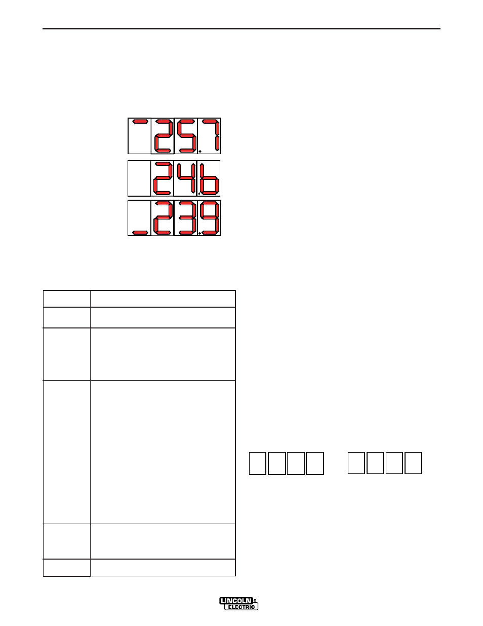
Synergic CV Voltage Display
Synergic CV programs feature an ideal voltage best
suited for most procedures. Use this voltage as a
starting point for the weld procedure and adjust if
needed for personal preferences.
When the
Voltage / Trim Knob
is rotated, the display
will show an upper or lower bar indicating if the volt-
age is above or below the ideal voltage.
•
Preset voltage
above ideal voltage.
(upper bar displayed)
•
Preset voltage
at ideal voltage.
(no bar displayed)
•
Preset voltage
below ideal voltage.
(lower bar displayed)
5. STATUS LED-
The status LED indicates system
status. Normal operation is a steady green light.
Note: During normal power-up, the LED may flash red
and/or green as the equipment performs self tests.
MSP-3 Multi-Process Panel
The center portion of the Power Feed-15M front case
enables selection of weld modes and fine tuning of
weld parameters within each weld mode. Preflow,
Postflow, Run In, Arc Control, Burnback, Postflow,
Crater and Spot are all adjustable with the SET and
SELECT toggle switches and 3 digit display.
6. SELECT toggle switch
- Toggles through the 8
adjustable welding parameters detailed above the
switch. A red LED is located next to each welding
parameter and is illuminated when the parameter is
active.
7. DISPLAY METER-
Shows the active value of the
weld parameter.
8. SET toggle switch-
changes the value of the
active weld parameter shown in the display meter.
Weld Mode
The Weld Mode selection is enabled by toggling the
SELECT toggle switch until the LED next to WELD
MODE is lit. The present mode number will be dis-
played. Toggling the SET toggle switch up or down
will increase or decrease the WELD MODE number.
The weld mode on the display will become the active
weld mode after 2 seconds of SET toggle switch inac-
tivity.
The last active weld mode is saved at power down
and will is automatically selected upon the next power
up of the feeder.
Preflow
The Preflow setting adjusts the amount of time the
shielding gas flows after the trigger is pulled and prior
to wire feeding and arc strike. Preflow times can be
adjusted from 0 to 2.5 seconds in 0.1 second incre-
ments.
To adjust the Preflow time, toggle the SELECT toggle
switch until the LED next to PREFLOW/POSTFLOW
is lit. The display will read:
The present Preflow time will be displayed.Toggle the
SET toggle switch up or down to change the Preflow
time to a new value.
P
r
E
F
L
o
Light
Condition
Steady Green
Blinking
Green
A l t e r n a t i n g
Green and
Red
Steady Red
Blinking Red
Meaning
System OK. Power source communicating normal-
ly with wire feeder and its components.
Occurs during a reset and indicates the
power source is identifying each component
in the system. This is normal for the first 10
seconds after power-up, or if the system con-
figuration is changed during operation.
Non-recoverable system fault. If the power
source or wire feeder status LED is flashing
any combination of red and green, errors are
present in the system.
Read the error code
before the machine is turned off.
Instructions for reading the error code are
detailed in the Service Manual. Individual
code digits are flashed in red with a long
pause between digits. If more than one code
is present, the codes will be separated by a
green light.
To clear the error, turn the power source
OFF, and then back ON to reset. See
Troubleshooting Section.
Non recoverable hardware fault. Generally
indicates a problem with the cables connect-
ing the wire feeder to the power source.
Not applicable.
POWER FEED 15M