Installation, Warning – Lincoln Electric IM761 POWER FEED 15M User Manual
Page 12
A-5
INSTALLATION
POWER FEED 15M
A-5
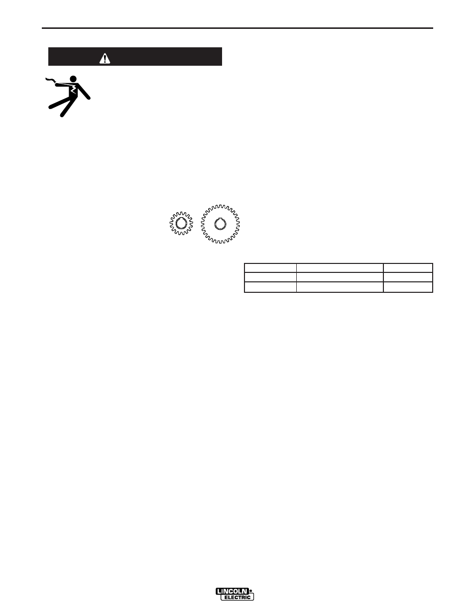
CHANGING THE DRIVE MOTOR GEAR RATIO
• Turn off input power at the weld-
ing power source before installa-
tion or changing drive roll and/or
wire guides.
• Do not touch electrically live parts
such as the wire drive or internal
wiring.
• When feeding with the gun trigger, the electrode
and wire drive mechanism are "hot" to work and
ground and could remain energized several sec-
onds after the gun trigger is released.
• Only qualified personnel should perform this
operation.
------------------------------------------------------------------------
Tools required:
• 1/4" hex key wrench
• 3/4" socket and ratchet wrench
• 9/16" socket and ratchet wrench
• 7/16" nut driver
• 5/16" nut driver
• Phillips screw driver
1. Remove the spool of electrode from the wire feeder.
2. Loosen the thumb screw at the wire drive and remove the
welding gun. Take the tension off the drive rollers and
open the tension handle.
3. Remove the outer wire guide, drive rolls and inner wire
guide.
4. Use a 7/16" nut driver to remove the gear cover.
5. Use 9/16" socket and ratchet wrench to remove the lower
drive roll hub retainer. Remove the lower drive roll hub.
6. With a Phillips screwdriver, remove the screw, washer
and collar holding the pinion gear. Remove the pinion
gear.
7. Remove the electrode lead by unscrewing the bolt using
a 3/4" socket and ratchet wrench.
8. With a 1/4" hex key wrench, loosen the socket head cap
screw securing the gun bushing. Remove the gun bush-
ing from the wire drive.
9. With a 5/16" nut driver remove the screws securing the
cover assembly protecting the display board. Lift out the
cover assembly enough so it does not overlap the wire
drive.
10. Use a 7/16" nut driver to remove the bolt at the top
securing the wire drive insulated panel to the sheet
metal case.
11. Use a 5/16" nut driver to remove the four screws
and washers holding the insulated panel to the
sheet metal bracket.
12. Lift the wire drive assembly partially out of the wire
feeder. With a Phillips screw driver, remove the
three screws and lock washers securing the
motor. Remove the motor.
13. Place the motor in the new position.
14. Assemble the three screws and lock washers
holding the wire drive motor.
15. Place the wire drive assembly inside the wire
feeder. With a 5/16" nut driver, assemble the four
screws and lock washers to hold the insulating
panel to the sheet metal bracket.
16. With a 7/16" nut driver, replace the bolt at the top
securing the wire drive insulated panel to the
sheet metal case.
17) Move DIP switch #8 on the Feed head board to
the appropriate position.
Gear Select
DIP Switch #8 Setting
Range
High Speed
ON
50 – 700 ipm
Low Speed
OFF
50 – 400 ipm
18. Reassemble the cover assembly protecting the
display board with a 5/16" nut driver.
19. Place the gun bushing in the wire drive and align
the threaded hole in the gun bushing with the hole
in the feed plate. With a 1/4" hex key, tighten the
socket head cap screw to secure the bushing in
the wire drive.
20. Reassemble the electrode and tighten the mount-
ing hardware with a 3/4" socket and ratchet
wrench.
21. Place the new gear on the motor shaft. Secure the
gear to the motor shaft with the collar, washer and
screw.
22. Reassemble the lower drive roll hub and lower
drive roll hub retainer.
23. Reassemble the gear cover.
24. Reassemble the inner wire guide, drive rolls and
outer wire guide.
25. Place the welding gun into the gun bushing and
secure with the thumb screw.
WARNING
Low Speed
High Torque
Gear
High Speed
Low Torque
Gear