Installation, Installing the lamp and arc sensor options, Warning – Lincoln Electric IM667 Mobiflex 400-MS User Manual
Page 14
A-7
INSTALLATION
MOBIFLEX 400-MS
A-7
INSTALLING THE LAMP AND ARC
SENSOR OPTIONS
(continued)
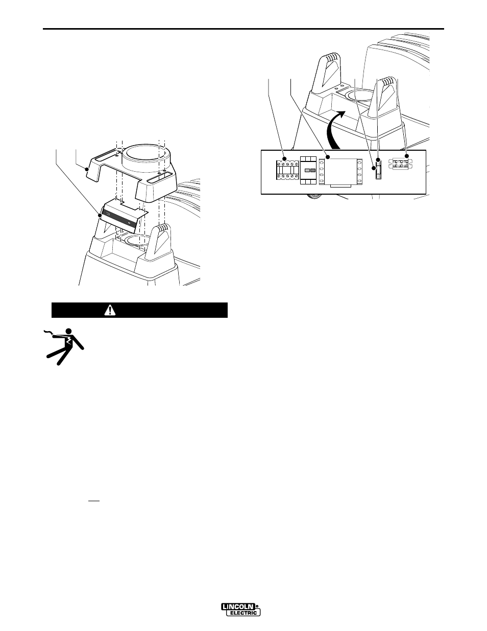
Loosen the four screws of the cover, lift the cover
around the arm and turn it 180 degrees, and allow it to
rest on the filter cover. Remove the control cover (Fig.
14, Item A), secured by four screws as shown. Route
the 13 ft. connecting cable through the grommet in the
control cover (cut an X as before).
ELECTRIC SHOCK can kill.
• Do not touch electrically live parts such
as internal wiring.
• Turn the input power off at the fuse box
before working on this equipment.
• Have a qualified person install and ser-
vice this equipment.
------------------------------------------------------------------------
Loop any extra cable inside the control box. Replace
the control cover and large cover over the handles.
MAKING CONNECTIONS AT THE CONTROL PANEL
Note: To insert conductors in Terminal Block, push in
on front opening with small screwdriver, and insert
conductor into corresponding top opening.
Note: GN is not the same potential as Ground.
Remove the jumper on the terminal block. Connect
the leads of the 13 ft. connecting cable according to
color (WH, BN, GN). Loop any extra cable inside the
control box. Replace the control cover and large cover
over the handles.
A
B
Fig. 14
A
B
C
D
E
Fuse
Terminal Block
Fuse Holder
Contactor
Starter/OL
Transformer
Fig. 15
WARNING