Installation, Mounting the extraction arm, Warning caution – Lincoln Electric IM667 Mobiflex 400-MS User Manual
Page 10
A-3
INSTALLATION
MOBIFLEX 400-MS
A-3
Only qualified personnel should install, use or service
this equipment.
-----------------------------------------------------------------------
Leave the tape and plastic packaging on the
extraction arm sections until the arm is complete-
ly installed (including mounting the hood). The arm is
spring-balanced to compensate for the weight of the
hood and will spring out quickly if it is not mounted
securely, with the hood in place.
------------------------------------------------------------------------
The Mobiflex 400-MS base unit is packed with the
right-front (when facing the inlet) wheel locked. To
unlock the wheel: using a sturdy screwdriver, push
down (hard) on the tab over the wheel, until it clicks
and the gold tab (underneath) pops up.
------------------------------------------------------------------------
MOUNTING THE EXTRACTION ARM
After unpacking the base unit, stabilize it while mount-
ing the arm by re-locking the front wheel. To lock the
wheel, with your shoe or a sturdy screwdriver, push
on the gold tab (on the right front wheel) until it snaps
down.
The rotating hinge of the arm comes in three pieces:
Metal rotating hinge, red plastic ring, and clamping
pin. Refer to Figure 1.
1. Slip the clamping pin through the hole in the rotat-
ing rod.
2. Fit the red plastic ring over the clamping pin.
3. Rotate the clamping pin to snap it into place on the
U-shaped indents on the red plastic ring.
The lip of the ring should fit securely against the top
edge of the rotating flange, yet rotate with the rod.
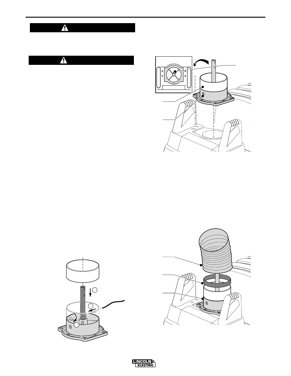
Remove the red plastic cover from over the handles
by removing the four Phillips-head screws. Mount the
rotating hinge assembly over the inlet (Fig. 2, Item C)
so the cable hole (Fig. 2, Item B) is in the front. Use
the eight (1.25”) bolts supplied with the Mobiflex to
secure the rotating hinge assembly.
Place one rubber seal (Fig. 3, Item B) fully onto the
red plastic ring. Roll the top half of the rubber seal
down onto itself and slide the connection hose (Fig. 3,
Item A) over the red plastic ring (Fig. 3, Item C). Roll
the rubber seal up over the end of the connection
hose. If installing a lamp kit, leave the red cover loose
for further installation procedures. If not, replace the
cover over the large handles and secure with the four
phillips-head screws.
WARNING
CAUTION
2
1
3
Fig. 1
C
B
A
Fig. 3
B
C
A
Fig. 2
clamping
pin
red plastic ring
rotating rod
red plastic ring
(when in place)
rotating hinge
assy