Installation – Lincoln Electric IM991 LN-25 PRO DUAL POWER User Manual
Page 18
A-9
INSTALLATION
LN-25™ PRO DUAL POWER
A-9
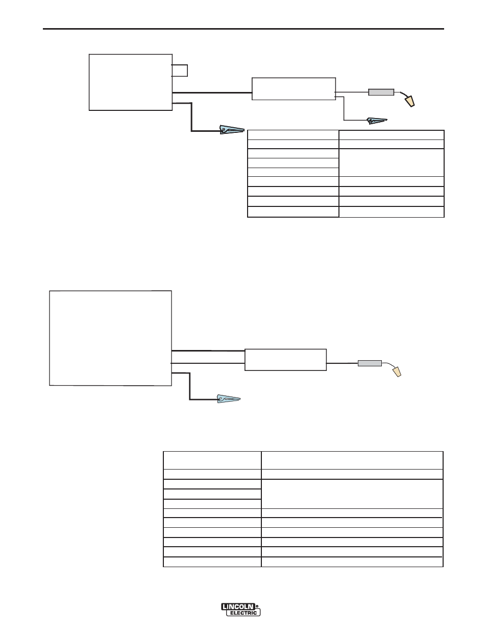
CV Power Source with Twist-Mate Connectors and
no Remote/Local Switch. (See Figure A.9)
Place CV/CC switch in the feeder in the "CV" position.
CV-250
CV-300
CV-305
Work
Electrode
Jump er
W or k clip
LN-25™ PRO DUAL POWER
FIGURE A.9
K#
K2614-1, -3
KP1695-XX
KP1696-XX
KP1697-XX
See Magnum Literature
K1841-
K484
Description
LN-25™ PRO Dual Power
Drive Roll Kit
Welding Gun
CV power Source
Welding Cables
Jumper Plug kit
CV Power Source with 24 or 42 VAC
(See Figure A.10)
If present, place the power source Remote/Local
Switch in the Remote position.
Place CV/CC switch in the feeder in the "CV" position.
CV Power Source
CV-305
CV-400
CV-655
DC-400
DC-655
V-350
V-450
Work
Electrode
Control Cable
• Ranger 250
• Ranger 305
• Vantage 300
• Vantage 400
• Vantage 500
• SAE’s Require
K-385-2
• Classic’s Require
Wire Feed Module
• STT-II
LN-25™ PRO DUAL POWER
K#
K2614-1, -3
KP1695-XX
KP1696-XX
KP1697-XX
K1797-xx
K2335-1
See Magnum Literature
K852-95
Description
LN-25 PRO Dual Power
Drive Roll Kit
Control Cable
Adapter for Competitive Power Sources
Welding Gun
CV power source
Welding Cables
Twist-Mate Cable Plug
FIGURE A.10