Operation, Arclink status led, Cold feed/gas purge switch – Lincoln Electric IM876 eCELL WIRE DRIVE SYSTEM User Manual
Page 22
B-4
OPERATION
B-4
eCELL
™
WIRE DRIVE SYSTEM
1. ARCLINK STATUS LED
The status LED indicates system status. Normal
operation is a steady green light.
Note: During normal power-up, the LED may flash
red and/or green as the equipment performs self tests.
LED condition
Definition
Steady green
System okay. The power source and wire feed-
er are communicating normally.
Blinking green
Occurs during a reset and indicates the power
source is identifying each component in the
system. This is normal for the first 10 seconds
after power-up, or if the system configuration is
changed during operation.
Alternating green Non-recoverable system fault. If the power
source or wire feeder status LED is flashing
any combination of red and green, errors are
present in the system. Read the error code
before the machine is turned off.
Instructions for reading the error code are
detailed in the Service Manual. Individual code
digits are flashed in red with a long pause
between digits. If more than one code is pre-
sent, the codes will be separated by a green
light.
To clear the error, turn the power source OFF,
and then back ON to reset. See troubleshooting
section.
Steady red
Non recoverable hardware fault. Generally indi-
cates a problem with the cables connecting the
wire feeder to the power source.
Blinking red
Not applicable.
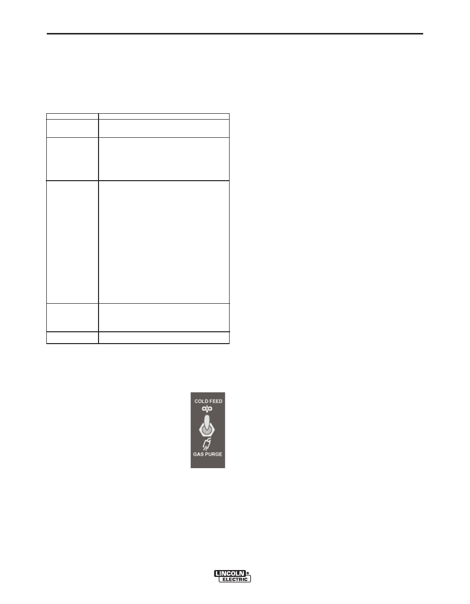
2. COLD FEED/GAS PURGE SWITCH
Cold Feed and Gas Purge are combined into a single
spring centered toggle switch.
To activate Cold Feeding, hold the switch
in the UP position. The wire drive will feed
electrode but neither the power source nor
the gas solenoid will be energized. Adjust
the speed of cold feeding by rotating the
WFS knob. Cold feeding, or "cold inching"
the electrode is useful for threading the
electrode through the gun.
Hold with toggle switch in the DOWN position to acti-
vate Gas Purge and let the shielding gas flow. The
gas solenoid valve will energize but neither the power
source output nor the drive motor will be turned on.
The Gas Purge switch is useful for setting the proper
flow rate of shielding gas. Flow meters should always
be adjusted while the shielding gas is flowing.
3. 5 - P I N A M P H E N O L F O R A R C L I N K
DIGITAL CONTROL CABLE
(See Installation Section for details)
and red