Installation, Warning – Lincoln Electric IM876 eCELL WIRE DRIVE SYSTEM User Manual
Page 13
A-6
INSTALLATION
eCELL
™
WIRE DRIVE SYSTEM
A-6
EXTERNAL SHUTDOWN SIGNAL
ELECTRIC SHOCK can kill.
• Turn the input power OFF at the dis-
connect switch before working on
this equipment.
• Do not touch electrically hot parts.
• Only qualified personnel should install, use or
service this equipment.
------------------------------------------------------------------------
The eCell™ Wire Drive includes one input for an
external shut-off circuit. The circuit interrupts the trig-
ger signal and stops the welding process in the event
of a fault. The most common use is for a flow switch
when using water cooled guns or torches.
The external device must have "normally closed" con-
tacts.
Do not use the external shut-off circuits for safety or
emergency stops.
To connect to the shutoff circuit:
1. Turn off power to the wire feeder at the disconnect
switch.
2. Remove the screws securing the wrap-around and
door assembly.
3. Locate leads 570 and 570A/570B in the harness
for external shut-off switch. (See Figure A.4)
4. Wire the external equipment to the leads. Route
the wiring for the external equipment through the
rear of the wire feeder.
5. Reassemble the wrap-around and door assembly.
6. Restore power.
FIGURE A.4
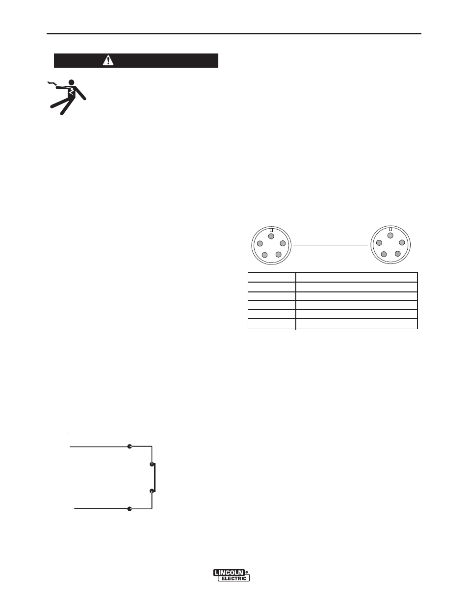
DIGITAL CONTROL CABLE, K1543-XX
ArcLink/LincNet control cables are special high quality
cables for digital communication. The cables are cop-
per 5 conductor cable in a SO-type rubber jacket.
There is one 20 gauge twisted pair for network com-
munications. This pair has an impedance of approxi-
mately 120 ohms and a propagation delay per foot of
less than 2.1 nanoseconds. There are two 12 gauge
conductors that are used to supply 40VDC to the net-
work. The fifth wire is 18 gauge and is used as an
electrode sense lead.
Use of non-standard cables may lead to system shut-
downs, poor arc starting and wire feeding problems.
The control cables connect the power source to the
wire feeder, and the wire feeder to other wire feeders.
PIN
FUNCTION
A
Digital I/O
B
Digital I/O
C
"67" voltage sense
D
40 VDC
E
Common
Use a maximum of 250 feet (76.2m) of control cable
between components.
WARNING
EXTERNAL
DEVICE
570
570A/570B
E
D
C
B
A
E
D
C
B
A
POWER SOURCE
WIRE FEEDER