Installation, Warning – Lincoln Electric IM876 eCELL WIRE DRIVE SYSTEM User Manual
Page 17
SHIELDING GAS CONNECTION
CYLINDER may explode if damaged.
• Keep cylinder upright and chained to
support.
• Keep cylinder away from areas where
it may be damaged.
• Never lift welder with cylinder attached.
• Never allow welding electrode to touch cylinder.
• Keep cylinder away from welding or other live elec-
trical circuits.
---------------------------------------------------------------------------
BUILD-UP OF SHIELDING GAS may
harm health or kill.
• Shut off shielding gas supply when
not in use.
SEE AMERICAN NATIONAL STANDARD Z-49.1,
" S A F E T Y I N W E L D I N G A N D C U T T I N G " P U B -
LISHED BY THE AMERICAN WELDING SOCIETY.
------------------------------------------------------------------------
Maximum inlet pressure is 100 psi. (6.9 bar.)
Install the shielding gas supply as follows:
1. Secure the cylinder to prevent it from falling.
2. Remove the cylinder cap. Inspect the cylinder
valves and regulator for damaged threads, dirt,
dust, oil or grease. Remove dust and dirt with a
clean cloth. DO NOT ATTACH THE REGULATOR
IF OIL, GREASE OR DAMAGE IS PRESENT!
Inform your gas supplier of this condition. Oil or
grease in the presence of high pressure oxygen is
explosive.
3. Stand to one side away from the outlet and open
the cylinder valve for an instant. This blows away
any dust or dirt which may have accumulated in the
valve outlet.
4. Attach the flow regulator to the cylinder valve and
tighten the union nut(s) securely with a wrench.
Note: if connecting to 100% CO
2
cylinder, insert
regulator adapter between regulator and cylinder
valve. If adapter is equipped with a plastic washer,
be sure it is seated for connection to the CO
2
cylin-
der.
5. Attach one end of the inlet hose to the outlet fitting
of the flow regulator. Attach the other end to the
welding system shielding gas inlet. Tighten the
union nuts with a wrench.
6. Before opening the cylinder valve, turn the regulator
adjusting knob counterclockwise until the adjusting
spring pressure is released.
7. Standing to one side, open the cylinder valve slowly
a fraction of a turn. When the cylinder pressure
gage stops moving, open the valve fully.
8. The flow regulator is adjustable. Adjust it to the flow
rate recommended for the procedure and process
being used before making a weld.
A-10
INSTALLATION
eCELL
™
WIRE DRIVE SYSTEM
A-10
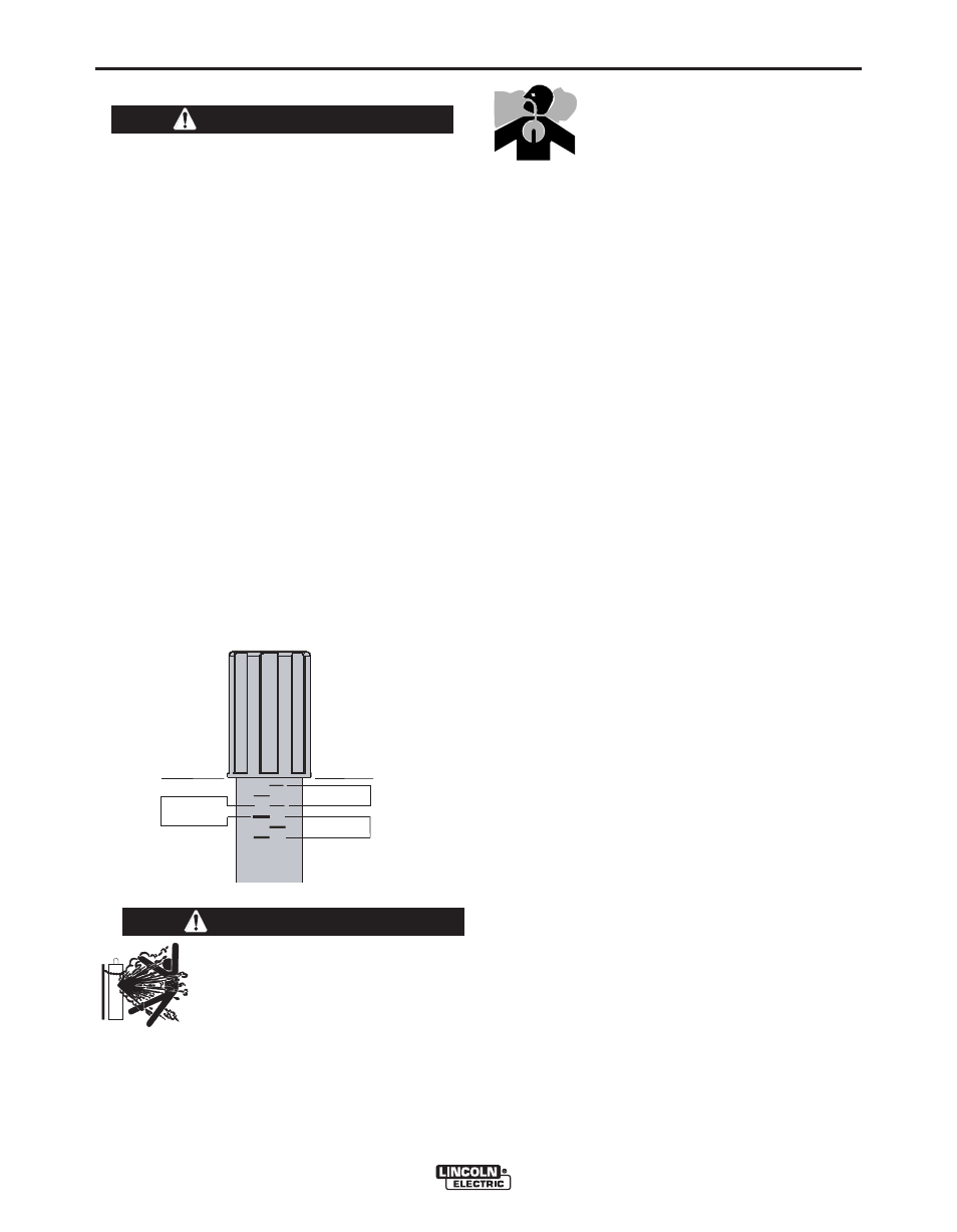
PRESSURE ARM ADJUSTMENT
ELECTRIC SHOCK can kill.
• Turn the input power OFF at the welding power
source before installation or changing drive
rolls and/or guides.
• Do not touch electrically live parts.
• When inching with the gun trigger, electrode
and drive mechanism are "hot" to work and
ground and could remain energized several sec-
onds after the gun trigger is released.
• Only qualified personnel should perform mainte-
nance work.
------------------------------------------------------------------------
The pressure arm controls the amount of force the
drive rolls exert on the wire. Proper adjustment of
both pressure arms gives the best welding perfor-
mance.
Set the pressure arm as follows (See Figure A.9):
Aluminum wires
between 1 and 3
Cored wires
between 3 and 4
Steel, Stainless wires
between 4 and 6
For best results, use the same setting on both pres-
sure arms. This maximizes traction of the drive rolls
while minimizing wire deformation.
FIGURE A.9
WARNING
ALUMINUM
OUTERSHIELD
METALSHIELD
INNERSHIELD
STEEL
STAINLESS
CORED WIRES
SOLID WIRES
6
1
3 2
5 4
WARNING