Installing the motherboard – Elitegroup 945GSED-I (V1.0) User Manual
Page 22
18
Installing the Motherboard
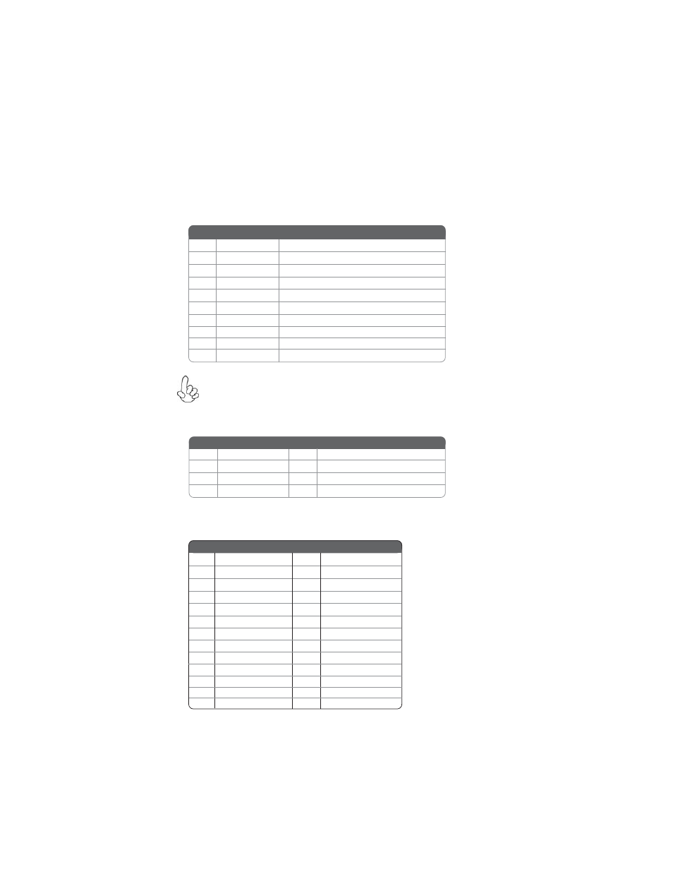
F_USB1: Front Panel USB header
The motherboard has four USB ports installed on the rear edge I/O port array.
Additionally, some computer cases have USB ports at the front of the case. If you
have this kind of case, use auxiliary USB connector to connect the front-mounted
ports to the motherboard.
Please make sure that the USB cable has the same pin assignment as
indicated above. A different pin assignment may cause damage or system
hang-up.
1
USBPWR
Front Panel USB Power
2
USBPWR
Front Panel USB Power
3
USB_FP_P0-
USB Port 0 Negative Signal
4
USB_FP_P1-
USB Port 1 Negative Signal
5
USB_FP_P0+
USB Port 0 Positive Signal
6
USB_FP_P1+
USB Port 1 Positive Signal
7
GND
Ground
8
GND
Ground
9
Key
No pin
10
USB_FP_OC0
Overcurrent signal
Pin
Signal Name Function
DIO1: DIO header
2
GPO 33
3
GPI 6
4
GPO 34
Pin
Signal Name Pin
Signal Name
5
GPI 7
6
GPO 39
7
GND
8
GND
1
GPI 38
LPT2: Onboard parallel port header
This is a header that can be used to connect to the printer, scanner or other devices.
1
STROBE
14
AFD
2
PD0
15
ERROR
3
PD1
16
INIT
4
PD2
17
SLCTIN
5
PD3
18
Ground
6
PD4
19
Ground
7
PD5
20
Ground
Pin Signal Name Pin Signal Name
8
PD6
21
Ground
9
PD7
22
Ground
10
ACK
23
Ground
11
BUSK
24
Ground
12
PE
25
Ground
13
SLCT
26 Key