Grounding the chassis, Figure 14, Grounding poi – Brocade 6910 Ethernet Access Switch Hardware Installation Guide User Manual
Page 29
Brocade 6910 Ethernet Access Switch Hardware Installation Guide
13
53-1002650-02
2
Grounding the Chassis
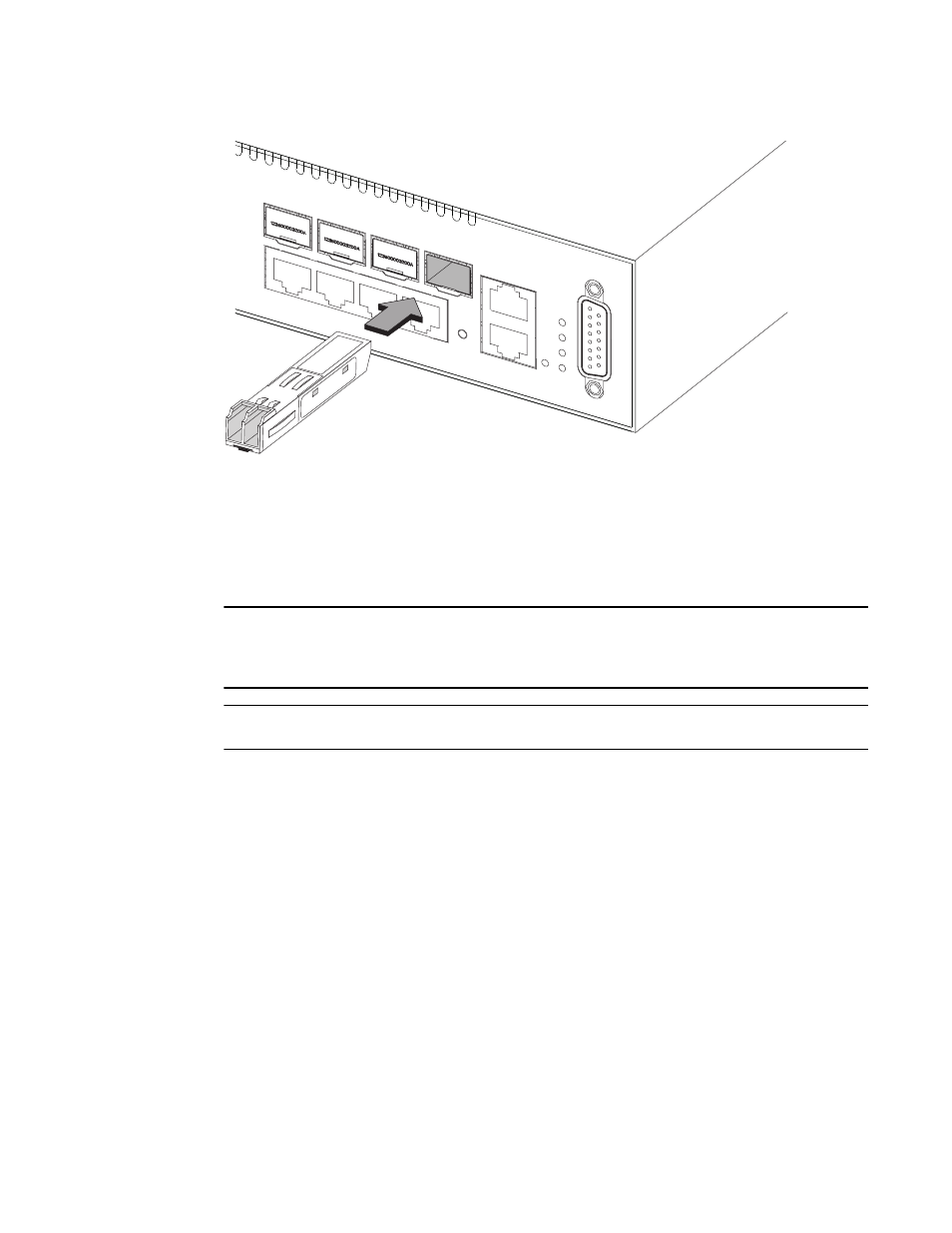
These switches support SFP-compatible transceivers. To install an SFP transceiver, do the
following:
1. Consider network and cabling requirements to select an appropriate SFP transceiver type.
2. Insert the transceiver with the optical connector facing outward and the slot connector facing
down. Note that SFP transceivers are keyed so they can only be installed in one orientation.
3. Slide the SFP transceiver into the slot until it clicks into place.
NOTE
SFP transceivers are hot-swappable. The switch does not need to be powered off before installing
or removing a transceiver. However, always first disconnect the network cable before removing a
transceiver.
NOTE
SFP transceivers are not provided in the switch package.
Grounding the Chassis
Before powering on the switch, ground the switch to earth as described below.
1. Ensure that the rack on which the switch is to be mounted is properly grounded and in
compliance with ETSI ETS 300 253.
2. Ensure that there is a good electrical connection to the grounding point on the rack (no paint or
isolating surface treatment).
3. Disconnect all power cables to the switch.
4. The switch chassis is connected internaly to 0 V. This circuit is connected to the grounding
terminal on the front of the switch. The surface area around this terminal is not painted in
order to provide for a good connection. Attach a 18 AWG stranded copper wire to the grounding
terminal on the switch.
5. Then attach the grounding wire to the ground point on the rack.
FIGURE 14
GROUNDING POINT