Step 1, Step 4, Step 6 – Anthro Fit Standard Unit 24/30/36/48 Assembly Instructions User Manual
Page 2: Step 2, Step 5, Step 3
Anthro Corporation Technology Furniture
®
10450 SW Manhasset Drive Tualatin, Oregon 97062
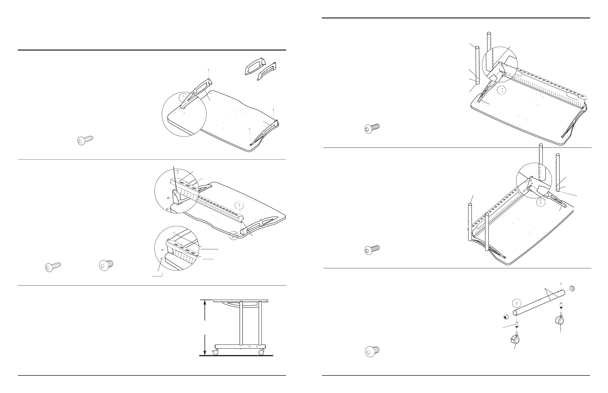
Step 1
Place your Worksurface onto the fl oor with the pre-
drilled holes facing upward.
Position the Support Brackets onto the Worksurface and
align two of the holes on each Support Bracket with the
predrilled holes on the Worksurface.
Loosely secure each Support Bracket to the Worksurface
using two Wood Screws per Support Bracket.
NOTE: fi t Small Support X & Y, to be used in place of the
Support Brackets
(24” only).
anthro.com
Step 4
Attach a Vertical Leg by installing two Support Screws
through the Support Bracket-A into holes 1 & 3 from the
top (non-coped end) of a Leg.
Repeat for the second Vertical Leg to be installed to
Support Bracket-A.
Step 6
Insert two End Caps into the ends of both Base Tubes.
Install two Caster Inserts into each Base Tube and
secure with one Insert Screw per Insert.
Insert one Locking and one Non-Locking Caster into
each Caster Insert of a Base Tube as shown.
Questions? 1-800-325-3841
Support Screw
325-5010-00
Step 2
Place the Back Trough onto the Worksurface, between the
installed Support Brackets (from Step 1).
Align the two threaded holes on each end of the Back
Trough with those on both Support Brackets. Carefully,
thread one Button Head Screw through the Support
Bracket, into the Back Trough. Repeat for remaining three
Button Head Screws.
Insert two Wood Screws through the two remaining holes
on the Back Trough fl ange (which should be aligned with two
predrilled holes on the Worksurface) and tighten into place.
Step 5
Attach the remaining Vertical Legs to Support Bracket-B
using the same procedure used in Step 5.
NOTE: Make certain to install the Vertical Legs into the same
holes used in Step 5.
Support Screw
325-5010-00
3
/
4
” Wood Screw
325-5106-00
3
/
4
” Wood Screw
325-5106-00
(
1
/
4
-20 X .50”) Button Head Screw
325-5003-00
Insert Screw
(with pink threads)
325-5052-00
Locking
Caster
Support Bracket-B
FIRST: Install the Button Head Screws
FIRST
FIRST
SECOND: Install the Wood Screws
Back Trough
SECOND:
Back Support Flange
Support Bracket-A
Support Bracket-B
Caster Inserts placed
into the large holes
Leave these two side holes open
Non-Locking
Caster
Hole 1=29” Final Worksurface Height
Support Bracket-A
Support Bracket-B
Hole 1
Top
(non-coped)
(non-coped)
end
Bottom
(coped)
end
Hole 3
Hole 1
Hole 3
Top
(non-coped)
end
Bottom
(coped)
end
NOTE: Make certain to install the Back
Trough in front of the Support Brackets
Threaded Holes
24”/30”/36”/48” Standard Unit
Assembly Instructions
fi t Small Support X & Y
(24” Standard Unit Only)
Step 3
Determine the best height for your Worksurface. These
instructions will place your Worksurface 29” from the
fl oor using the standard 3” casters.
For a fi nal Worksurface height that is lower than 29”,
adjust one hole down for each inch of variance desired.
NOTE: Your Worksurface location may be changed after your
Standard Unit has been completely assembled by repeating
Steps 5 & 6.
29”