Step 1, Step 2, Step 4 – Anthro Fit Standard Unit 60/72 Assembly Instructions User Manual
Page 2: Step 5, Step 3, Step 6, Step 7, Step 8
Anthro
Corporation Technology Furniture
®
10450 SW Manhasset Drive Tualatin, Oregon 97062
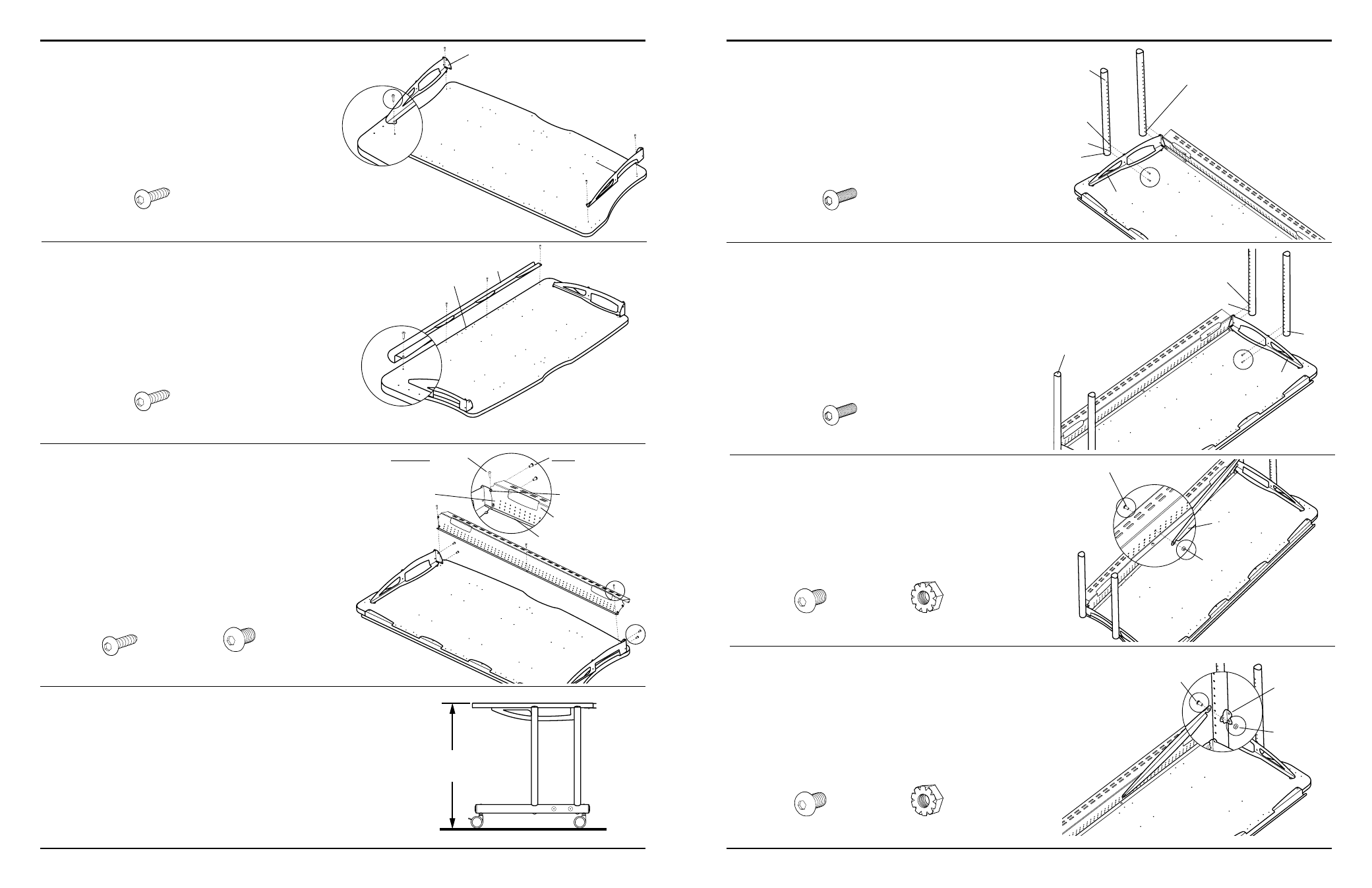
Step 1
Place your Worksurface onto the floor with the predrilled
holes facing upward.
Position the Support Brackets onto the Worksurface and
align two of the holes on each Bracket with the predrilled
holes on the Worksurface.
Loosely secure each Support Bracket to the Worksurface
using two Wood Screws per Support Bracket.
Step 2.
Place the Front Lip onto the straight edge of the Shelf
and secure using four Wood Screws as shown.
anthro.com
Step 4
Determine the best height for your Worksurface.
These instructions will place your Worksurface 29" from
the floor using the standard 3" Casters. For a final Shelf
height that is lower than 29", adjust one hole down for
each inch of variance desired.
NOTE:.Your.Worksurface.height.may.be.changed.after.your.
Standard.Unit.has.been.completely.assembled.by.repeating.
Steps.5,.6,.7,.8.&.9.
Step 5
Attach a Vertical Leg by installing two Support Screws
through the Support Bracket-A into holes 1 & 3 from the
top (non-coped.end) of a Vertical Leg.
Repeat for the second Vertical Leg to be installed to
Support Bracket-A.
Support Screw
325-5010-00
Step 3
Position the Back Trough onto the Worksurface, between
the installed Support Brackets (as.shown).
Align the two threaded holes on each end of the Back
Trough with the holes on both Support Brackets. Carefully,
thread one Button Head Screw through the Support
Bracket, into the Back Trough. Repeat for remaining three
Button Head Screws.
Install three Wood Screws through the holes on the Back
Trough flange (which.should.be.aligned.with.three.predrilled.
holes.on.the.Worksurface).
Step 6
Attach the remaining Vertical Legs to Support Bracket-B
using the same procedure used in Step 5.
NOTE:.Make.certain.to.install.the.Vertical.Legs.into.the.same.
holes.used.in.Step.5.
Support Screw
325-5010-00
3
/
4
" Wood Screw
325-5106-00
3
/
4
" Wood Screw
325-5106-00
3
/
4
" Wood Screw
325-5106-00
(
1
/
4
-20 X .50") Button Head Screw
325-5003-00
29"
Questions? 1-800-325-3841
60"/72" wide Standard Unit
Step 7
Position a Buttress against the Back Trough, aligning the
holes on both Buttress and Back Trough.
Insert a Button Head Screw from the rear of the Trough, and
capture on the opposite side using a Keps Nut.
NOTE:.Just.hand.tighten.the.Keps.Nut.at.this.point..
Step 8
Position a Cross End on the opposite end of the Buttress
installed during Step 7.
Insert a Button Head Screw from the rear of the Buttress,
through the Cross End and capture on the opposite side
using a Keps Nut.
NOTE:.Just.hand.tighten.the.Keps.Nut.at.this.point.
(
1
/
4
-20 X .50") Button Head Screw
325-5003-00
(
1
/
4
-20) Keps Nut
325-5130-03
(
1
/
4
-20 X .50") Button Head Screw
325-5003-00
(
1
/
4
-20) Keps Nut
325-5130-03
Hole 1=29" Final Worksurface Height
Support Bracket-A
Support Bracket-B
Hole 1
Top
(non-coped)
end
Bottom
(coped)
end
Hole 3
Hole 1
Hole 3
Top
(non-coped)
end
Bottom
(coped)
end
Support Bracket-A
Support Bracket-B
Front Lip
Back Trough
Threaded holes
FIRST: Install the
Button Head Screws
SECONd: Install
the Wood Screws
Back Trough flange
NOTE: Make certain
to install the Back
Trough in front of the
Support Brackets
Keps Nut
Button Head Screw
Keps Nut
Button Head Screw
Straight Edge
Buttress flange
faces towards
the front
Cross End