Anthro printercart, Assembly instructions, Step 1 – Anthro PrinterCart 20H & 28H Assembly Instructions User Manual
Page 2: Step 2, Step 3, Step 4, Step 5, Step 6
Anthro PrinterCart
Assembly Instructions
Anthro Corporation Technology Furniture
®
10450 SW Manhasset Drive Tualatin, Oregon 97062
Step 1
Before proceeding, please review the Assembly Instructions of all Anthro Products you purchased and are planning
to include in this installation.
Decide on the shelf configuration that works best for you. Generally, customers place the large shelf at the top
of the legs and the small shelf at the bottom of the legs, and that’s how these instructions are organized. This
configuration leaves 18" clearance between the shelves on the 28" high cart and 10" clearance between the shelves
on the 20" high cart.
Shelves can be installed at any height (in 1" increments), so find the best configuration for you. If you need
help configuring your cart, just give us a call!
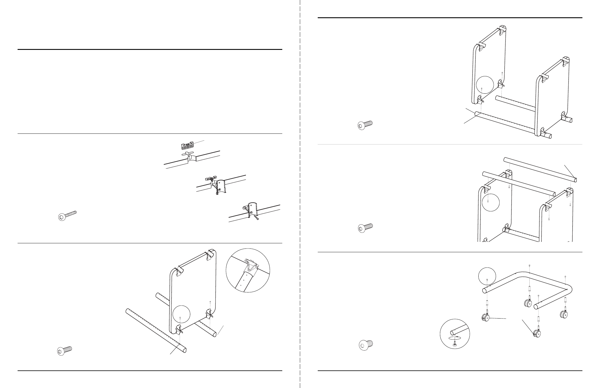
Step 2
Attach four Shelf Supports to each Shelf. Begin by first
installing a Shelf Clamp into the Shelf notch. Be sure
the pointed barbs face towards the outer Shelf edge.
Next, slide a Shelf Support into the recesses of the
Shelf Clamp and Shelf. Push in as far as possible.
Finally, secure with a Clamp Screw.
anthro.com
Step 3
Loosely attach a Shelf to the bottom hole (coped end)
of two Vertical Legs using two Support Screws.
NOTE: This will place your lower Shelf 20" from the floor
using the standard 2
3
/
8
" Casters.
Step 4
Loosely attach the remaining Shelf to Hole 2 from the
top (non-coped end) of the Vertical Leg Assembly (from
Step 3) using two Support Screws.
NOTE: Handle the Shelf Assembly carefully until the Cart
is fully assembled.
Step 5
Loosely attach the 3
rd
and 4
th
Vertical Legs to the
Shelf Assembly (from Step 4) using one Support
Screw per Shelf Support.
TIP: Use the holes in the Vertical Legs as a ruler to
ensure that your Support Screws are installed into the
correct locations.
Questions? 1-800-325-3841
First
Next
Finally
Support Screw
325-5010-00
Support Screw
325-5010-00
Clamp Screw
325-5086-03
Barbs
Support Screw
325-5010-00
Bottom (coped) end
Hole 12=20"
(using 2
3
/
8
" Casters)
Top (non-coped) end
Hole 2
Bottom (coped) end
Insert one Support Screw
through each Shelf Support
Step 6
Install all four Caster Inserts into the Base Tube and
secure with one Caster Screw per Insert.
Push the Casters, (locking ones in front) into the
Caster Inserts.
Caster Screw
(small pink patch on end)
325-5052-00
GLIDES ONLY
Thread each Glide
into the Glide Inserts
Locking
Casters