60” wide anthrocart, Assembly instructions, Step 1 – Anthro Large AnthroCarts 60W Assembly Instructions User Manual
Page 2: Step 3, Step 4, Step 5, Step 7, Step 2, Step 6, H24xx & h25xx
Anthro
®
Corporation Technology Furniture
®
10450 SW Manhasset Drive Tualatin, Oregon 97062
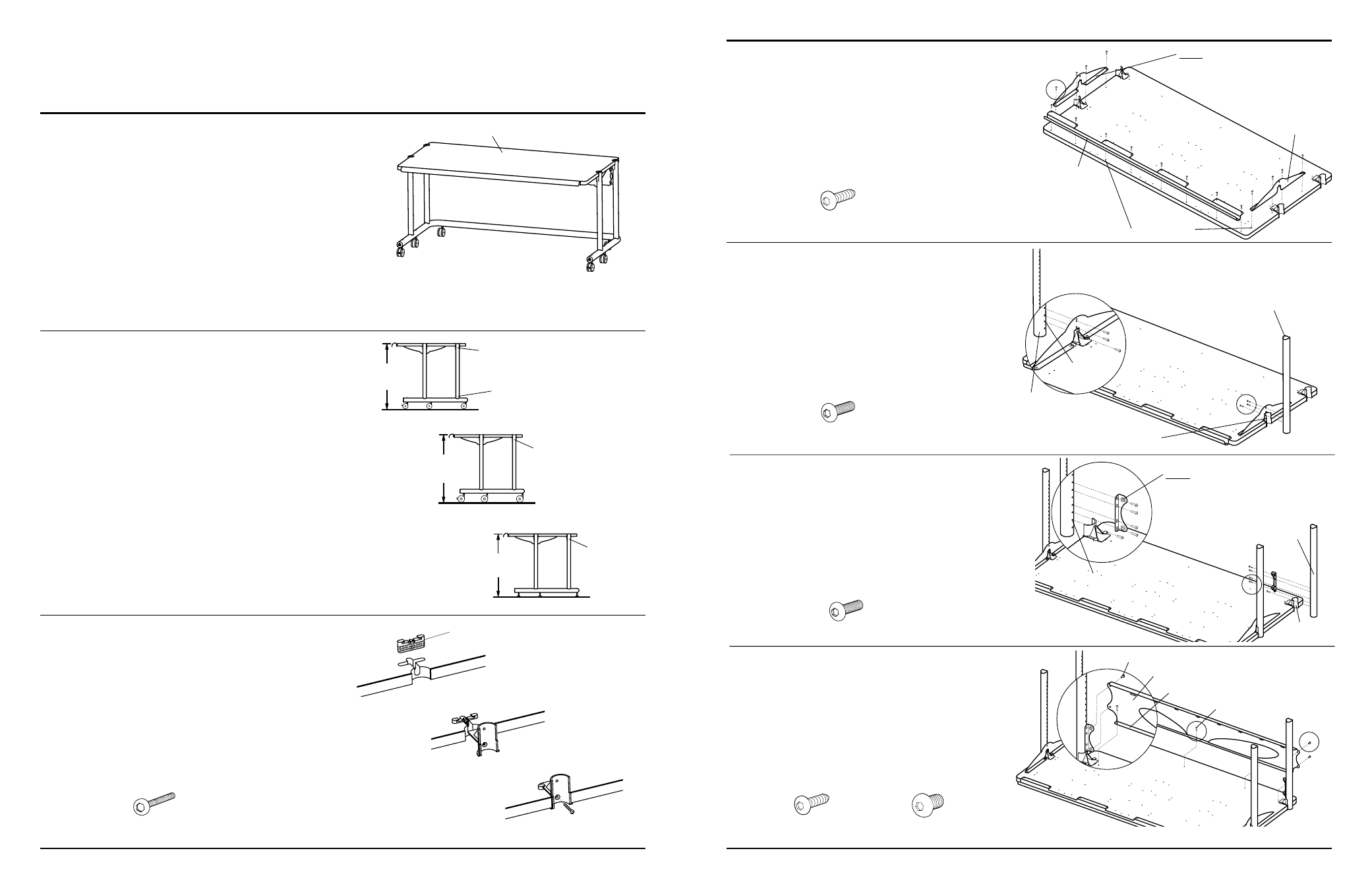
Step 1
These Instructions will cover both the H24xx & H25xx
60” Wide AnthroCart assembly. Before proceeding,
please review the Assembly Instructions of all Anthro
Products you purchased and are planning to include in
this installation.
These instructions will place your Shelf 28” from the
floor using the standard 2
3
/
8
” Casters.
Step 3
Attach all four Shelf Supports to the Shelf.
Begin by first installing a Shelf Clamp into the Shelf
notch. Be sure the pointed Barbs face towards the
outer Shelf edge.
Next, slide a Shelf Support into the recesses of the
Shelf Clamp and Shelf. Push in as far as possible.
Finally, secure with a Clamp Screw.
anthro.com
Step 4
Position both Bridge Side Gussets onto the Shelf
underside as shown. Align the predrilled holes on the
underside of the Shelf with those on the Gussets and
secure into place using a total of four Wood Screws per
Gusset.
Next, place the 56” Lip onto the front of the Shelf, aligning
the predrilled Holes of the Lip with those on the front of
the Shelf. Secure the Lip using a total of eight Wood Screws.
Step 5
Attach the front Vertical Legs by loosely installing one
Support Screw through a front Shelf Support into Hole
2 from the top (non-coped end) of a Leg.
Next, loosely install two Support Screws through a Side
Gusset into a corresponding Leg.
Repeat for remaining front Vertical Leg and Side Gusset.
Step 7
Place the Bridge Pan onto the Shelf between the
rear Vertical Legs. Secure the Pan to the Shelf by
first installing five Wood Screws through the Pan
flange into the Shelf.
Next, insert a Bracket Screw from the rear of the Cart
through the Pan and carefully thread into a Pan End
Bracket. Finally, repeat for the remaining Bracket
Screws and Pan End Bracket.
Questions? 1-800-325-3841
3
/
4
” Wood Screw
325-5106-00
Support Screw
325-5010-00
Step 2
Determine the best height for your Shelf.
Generally, a 28” high work surface works well for
most people and equipment.
For a final Shelf height that is higher or lower than 28”,
refer to the illustration shown at right to determine
which holes to attach your Shelf.
Your Shelf locations may be changed after your Cart
has been completely assembled by repeating Steps 5
& 6.
H24xx with 2
3
/
8
” Casters
H24xx4 with 4” Casters
H24xxGL with Glides
Hole 2=28”
Hole 3=27” (measured from the non-coped end)
Hole 4=26”
Hole 2=29”
Hole 3=28”
Hole 4=27”
Hole 2=25”
Hole 3=24”
Hole 4=22”
Coped end
28”
29”
25”
1
/
4
-20 X .375” Bracket Screw
325-5149-00
First
Next
Finally
Clamp Screw
325-5086-00
Barbs
H24xx & H25xx
60”Wide AnthroCart shown with 2
3
/
8
” Casters
Add 1” to overall height for 4” Casters
Subtract 3” from the overall height for Glides
28” High Shelf
3
/
4
” Wood Screw
325-5106-00
60” Wide AnthroCart
Assembly Instructions
NOTE: Make certain the Bridge Side
Gussets are oriented so the flanges
face toward the inside of the Cart.
Predrilled holes
NOTE: tighten all Wood and Bracket Screws after
they have ALL have been successfully installed.
Step 6
Attach the rear Vertical Legs by loosely installing one
Support Screw through the rear Shelf Supports into
Hole 2 of each Leg.
Next, position a Pan End Bracket against a rear Vertical
Leg. Secure into place by loosely installing four Support
Screws through the Bracket into Holes 3, 4, 6 & 7 from
the top of a rear Leg. Repeat for remaining Pan End
Bracket.
Support Screw
325-5010-00
Front Shelf Support
Hole 2
Top
(non-coped)
end
Hole 2
Bottom
(coped)
end
Rear
Shelf Support
NOTE: make certain the Pan End Brackets
are oriented so the PEM Nuts are facing
the front of the Cart & both Brackets are
LOOSELY installed.
Pan Flange
Bracket Screw
Wood Screw
Bridge Pan
56” Handle Lip
18” Side Gusset
Hole 2=28” using the 2
3
/
8
” Casters
Hole 2=29” using the 4” Casters
Hole 2=25” using the Glides
LOOSELY install
the rear Legs