72” anthrobench, Assembly instructions, Step 4 – Anthro AnthroBench II 72 Assembly Instructions User Manual
Page 2: Step 5, Step 6, Step 3, Step 2, Step 1, 29” or 35
Anthro
Corporation Technology Furniture
®
10450 SW Manhasset Drive Tualatin, Oregon 97062
anthro.com
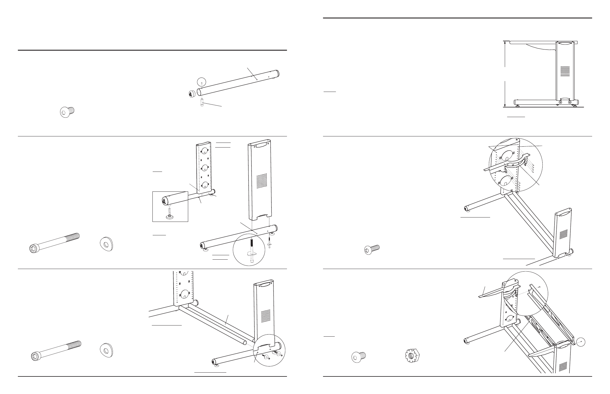
Step 4
Determine the desired height of your Shelf.
This instructions will
place the shelf at the top of the legs, either 29” or 35” from the
floor
(depending on which height Bench you purchased). If you
install 5” casters on your bench, they’ll make your Bench 5” taller.
The holes along the Leg Assemblies are spaced at 1” increments.
Adjusting either one hole up or down will modify the final Shelf
height by 1” respectively. Rotating the Glides will also provide
additional height adjustment.
NOTE: Your Shelf height can be adjusted at a later time if needed
by following Steps 5-8 below.
Step 5
Position the Left Bench Arm onto the Left Leg Assembly.
Align the top two openings of the Arm with hole 2 of the Leg
Assembly. Loosely install a Support Screw through the top
two holes of the Arm into the Leg.
Install the remaining six Support Screws into the Left Arm,
but do not fully tighten any of the Support Screws.
Repeat entire procedure for the Right Bench Arm on the Right
Leg Assembly.
Step 6
(requires a 3-Way Wrench)
Position a Bench Pan between the Arms, aligning the two
tabs on each Arm with the two holes in the lower corners
of a Pan. Insert a Pan Screw through the Pan and Arm
Tab capturing it with a Keps Nut
(but do not fully tighten).
Repeat this procedure for the remaining end of the Pan and
for the second Pan.
Tighten all Pan and Support Screws.
NOTE: the 3-Way Wrench can be used to assist in
tightening the Keps Nuts.
Questions? 1-800-325-3841
(
1
/
4
-20 X .5”) Pan Screw
325-5003-00
Support Screw
325-5010-00
Insert Screw
(small pink patch on end)
325-5052-00
Glide Inserts placed into
the large holes
Leave these two holes open
(
5
/
16
-18 X 4”) Bench Cap Screw
325-5166-00
Curved Washer
225-2050-00 or 225-3522-00
29” or 35”
Left Leg Assembly
Right Leg Assembly
Side holes
Cross Tubes
Leave top two
holes open
Hole 2
Left Leg Assembly
Right Leg Assembly
(
1
/
4
-20) Keps Nut
325-5130-03
(
5
/
16
-18 X 4”) Bench Cap Screw
325-5166-00
Curved Washer
225-2050-00 or 225-3522-00
Leave these two holes open
Lower holes
Arms
Second Pan shown installed
REMINDER: You may want to measure your
equipment to make sure it fits into the
selected Shelf location.
72” AnthroBench
Assembly Instructions
Left Bench Arm
Step 3
Position the Right Leg Assembly
(from Step 2) with two
Cross Tubes as shown. Insert one Bench Cap Screw with a
Curved Washer through a side hole, carefully threading the
Screw into the Cross Tube.
Repeat entire procedure for the remaining three
side holes.
Step 2
Orient one Bench Leg Assembly with one Base Tube Assembly
(from Step 1). The Glide Inserts should be facing down.
Insert one Bench Cap Screw through one Curved Washer, then
carefully insert through one of the lower holes on the Base
Tube, threading into the Right Leg Assembly.
Repeat this procedure for the remaining three lower holes on
the Right and Left Leg Assembly.
If you are installing Bench Glides, install them now by
threading one into each Glide Insert. If you are upgrading
to 5” Casters, install them now following their enclosed
instructions.
Left Leg
Assembly
Right Leg
Assembly
Glide Inserts
Thread one Glide
into each Glide Insert
A F T E R t h e B a s e
Tubes have been
installed to the Legs.
NOTE: Loosen these
Support Screws (if
needed) to allow the
Base Tube to install
easier.
Step 1
Install two Bench Glide Inserts into each Bench Base Tube and
secure with one Insert Screw per Insert.
Pop two End Caps into the ends of both Base Tubes.