STI 34188 User Manual
Page 2
Safety Technology International, Inc.
2306 Airport Road • Waterford, Michigan 48327-1209
Phone: 248-673-9898 • Fax: 248-673-1246
Toll Free: 800-888-4784 • E-mail: [email protected]
Web: www.sti-usa.com
Safety Technology International (Europe) Ltd.
Unit 49G Pipers Road • Park Farm Industrial Estate • Redditch
Worcestershire • B98 0HU • England • Tel: 44 (0) 1527 520 999
Fax: 44 (0) 1527 501 999 • Freephone: 0800 085 1678 (UK only)
E-mail: [email protected] • Web: www.sti-europe.com
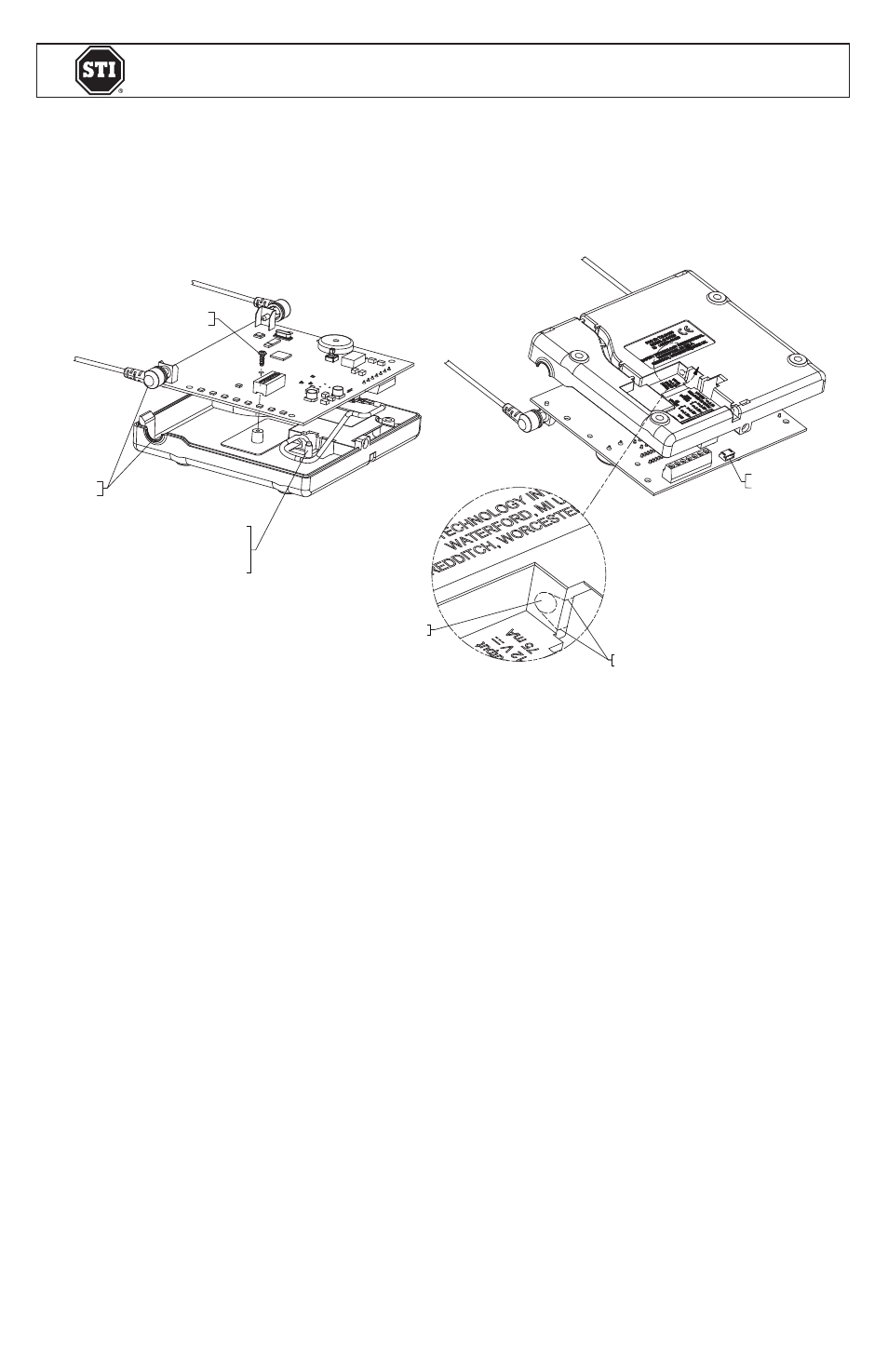
INSTALLATION OF STI-34188 8-ZONE RELAY BOARD
All specifications and information shown were current as of publication and are subject to change without notice.
STI-34188 JUNE 2012
A
AFTER DRILLING, CUT OUT THIS AREA
USING SIDE CUTTERS OR KNIFE
CABLE JACK TO RELAY BOARD
DRILL 5/32 in. (4mm)
DIAMETER HOLE
BE SURE TO ROUTE
CABLE AROUND POST AS
SHOWN AND PLUG
CABLE IN TO CONNECTOR
CIRCUIT BOARD MOUNTING SCREW
DETAIL A
ALIGN TO
ASSEMBLE
A
AFTER DRILLING, CUT OUT THIS AREA
USING SIDE CUTTERS OR KNIFE
CABLE JACK
TO RELAY BOARD
DRILL 5/32 in. (4mm)
DIAMETER HOLE
BE SURE TO ROUTE
CABLE AROUND POST AS
SHOWN AND PLUG
CABLE IN TO CONNECTOR
CIRCUIT BOARD
MOUNTING SCREW
DETAIL A
ALIGN TO
ASSEMBLE
CABLE INSTALLATION TO RECEIVER
1. Remove circuit board from base by removing circuit board mounting screw.
2. Drill 5/32 in. diameter hole in base as shown (circuit board must be removed.)
3. After drilling, cut out area as shown using side cutters or knife.
4. Route cable as shown and connect cable to jack on circuit board.
5. While replacing circuit board, gently pull cable from bottom of base to take up any
slack in cable occurred during installation.
SPECIFICATIONS
• Standby: 12 VDC; 0.01mA
• Max Operating: 12 VDC; 164mA
• Form “C” Contact Rating (resistive): 120 VAC, 3A; 28 VDC, 3A
WARRANTY
One year warranty on electro mechanical and electronic components.
Electronic warranty form at www.sti-usa.com/wc14.