STI 9609-SS User Manual
STI Safety
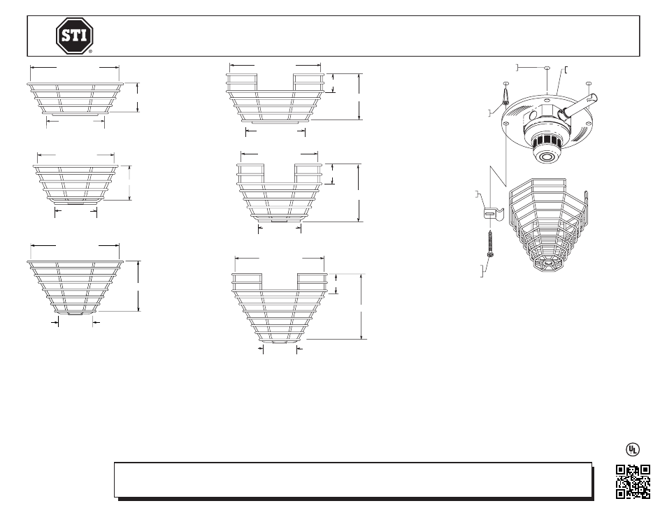
INSTALLATION OF STI CEILING MOUNTED SMOKE DETECTOR GUARDS
All specifications and information shown were current as of publication and are subject to change without notice.
9600 MARCH 2013
Safety Technology International, Inc.
2306 Airport Road • Waterford, Michigan 48327-1209
Phone: 248-673-9898 • Fax: 248-673-1246
Toll Free: 800-888-4784 • E-mail: [email protected]
Web: www.sti-usa.com
Safety Technology International (Europe) Ltd.
Unit 49G Pipers Road • Park Farm Industrial Estate • Redditch
Worcestershire • B98 0HU • England • Tel: 44 (0) 1527 520 999
Fax: 44 (0) 1527 501 999 • Freephone: 0800 085 1678 (UK only)
E-mail: [email protected] • Web: www.sti-europe.com
STI-9601
2.75 in.(70mm)
8.25 in.(210mm)
5 in.(127mm)
STI-9601-SS
STI-9604
STI-9604-SS
3.25 in.(83mm)
7 in.(178mm)
3 in.(76mm)
STI-9609
STI-9609-SS
4.6 in.(117mm)
8.25 in.(210mm)
3 in.(76mm)
4.25 in.(108mm)
8.25 in.(210mm)
STI-9602
5.75 in.(146mm)
1.5 in.(38mm)
STI-9605
STI-9605-SS
7.125 in.(181mm)
4.5 in.(114mm)
1.5 in.(38mm)
3.9 in.(99mm)
STI-9610
6 in.(152mm)
8.25 in.(210mm)
1.5 in.(38mm)
3 in.(76mm)
STI-8170 BACKPLATE
(OPTIONAL)
DRILL (4) .25 in.
6.3mm HOLES
19033 ANCHOR
(4) PROVIDED
19020 CLAMP
(4) PROVIDED
19013 SCREWS
#10 x 1 1/2 in.
(4) PROVIDED
SERVICE
1. Periodic cleaning of the smoke detector is required so dust and other matter
do not accumulate.
2. To service the smoke sensor unit, loosen but do not remove the (4) screws
rotate clamps and carefully remove wire guard.
OPTIONAL ACCESSORIES
1. SUB-82 - #8 x 1 1/2” spanner tamper resistant stainless steel screw kit.
2. 19038 - #8 spanner bit with 5/16” hex drive.
APPROVALS
STI-9601, STI-9602, STI-9604, STI-9605
UL Listed No. S3504 for use with Listed low profile smoke detectors
STI-9609, STI-9610
UL Listed No. S3504 for use with Listed high profile smoke detectors
IMPORTANT
Do not attempt to install the wire guard until the smoke sensor has been tested and in proper working
order according to the manufacturer’s installation instructions furnished with the sensor unit.
INSTALLATION
1. Center the wire guard over existing smoke detector.
2. Mark and drill (4) mounting holes (see pictorial for size). Insert anchor into ceiling.
NOTE: If lag
shields and lag bolts are used, make sure anchor is flush with surface. Position guard, insert lag bolts
and tighten. Length of bolt should be selected to assure full thread engagement in anchor.
3. STI-8170 BACKPLATE - STI recommends the use of this plate on all unstable mounting surfaces.
4. Insert screws through clamps and backplate (if used) and screw into anchors; but do not tighten.
5. Position guard over detector, slide clamps onto top wire of guard and tighten screws.
STI-9610
6 in.(152mm)
8.25 in.(210mm)
1.5 in.(38mm)
3 in.(76mm)
STI-8170 BACKPLATE
(OPTIONAL)
DRILL (4) .25 in.
6.3mm HOLES
19033 ANCHOR
(4) PROVIDED
19020 CLAMP
(4) PROVIDED
19013 SCREWS
#10 x 1 1/2 in.
(4) PROVIDED
Electronic warranty form at www.sti-usa.com/wc14