STI V6200WIR4 User Manual
Pc board, Nc com no gd v+ rs1 rs2 keysw
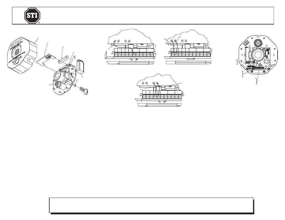
INSTALLATION OF STI-34071 STI Wireless Conversion Board for STI-6200 & STI-6400
All specifications and information shown were current as of publication and are subject to change without notice.
34071 NOV2012
Safety Technology International, Inc.
2306 Airport Road • Waterford, Michigan 48327-1209
Phone: 248-673-9898 • Fax: 248-673-1246
Toll Free: 800-888-4784 • E-mail: [email protected]
Web: www.sti-usa.com
Safety Technology International (Europe) Ltd.
Unit 49G Pipers Road • Park Farm Industrial Estate • Redditch
Worcestershire • B98 0HU • England • Tel: 44 (0) 1527 520 999
Fax: 44 (0) 1527 501 999 • Freephone: 0800 085 1678 (UK only)
E-mail: [email protected] • Web: www.sti-europe.com
CONTINUOUS SIGNALLING (DEFAULT FOR STI-6400WIR):
Add the blue “NC” wire to the existing reed switch wire
only on the left RS1 terminal next to the V+ terminal.
Important: Do not place in right RS1 terminal
(Note: The RS1 terminal must be used together with
the reed switch wire or these devices will not function
properly.)
Figure 2
Figure 1
Figure 3
TERMINAL BLOCK
(SEE BELOW)
JP5
JP2
JP4
JP3
JP7
SWITCH
ALARM
DURATION
ALARM VOLUME SWITCH
TRIP DELAY SWITCH
ARMING SWITCH
(FACTORY DEFAULT SETTINGS)
(ON)
(ON)
(OFF)
(OFF)
(OFF)
TERMINAL BLOCK
FOR COMPLETE ALARM OPTIONS
AND SWITCH SETTINGS SEE CHART
ON REVERSE SIDE.
PC BOARD
JP5
JP2
JP4
JP3
JP7
SWITCH
ALARM
DURATION
ALARM VOLUME SWITCH
TRIP DELAY SWITCH
ARMING SWITCH
)
(
FACTORY DEFAULT SETTINGS
(FACTORY DEFAULT SETTINGS)
(ON)
(ON)
(OFF)
(OFF)
(OFF)
WIRES FROM RETRO PCB
TO 9V BATTERY
WIRES FROM STOPPER PCB
TO RETRO PCB
BLUE “NC” WIRE
GREEN “COM” WIRE
WIRELESS TRANSMITTER PCB
EXIT ALARM
BASE ASSEMBLY
EXIT ALARM COVER
TRANSMITTER PCB
REED SWITCH
TRANSMITTER MOUNTING
SLOTS
9 VOLT BATTERY
TAMPERPROOF SCREW
EXIT ALARM BASE ASSEMBLY
NC Com
GD
V+
NC Com
GD
V+
NC Com
GD
V+
CONTINUOUS
SIGNALING
SIGNAL ONLY WITH
ALARM SWITCH ON
EXTERNAL POWER
(+12VDC)
NC COM NO GD V+
RS1
RS2
KEYSW
STEP 3: CONFIGURED WIRES
FROM TRANSMITTER
PCB TO STOPPER PCB
STEP 4: WIRES FROM
STOPPER PCB TO
TRANSMITTER PCB
STEP 5: WIRES FROM
TRANSMITTER PCB TO
9 VOLT BATTERY
NC COM NO GD V+ RS1
RS2 KEYSW
NC COM NO GD V+ RS1
RS2 KEYSW
NC COM NO GD V+ RS1
RS2 KEYSW
STOPPER PCB
BLUE
BLACK
BLUE
RED
GREEN
STANDARD STI-6400 INSTALLATION:
1. (Fig. 1) Remove tamperproof screw and cover.
Disconnect 9 Volt battery. Remove reed switch from
mounting location letting it hang freely.
2. Insert STI wireless transmitter PCB into mounting
slots. Place the board with the 9 Volt connector facing
inward towards the sounder.
3. (Fig. 2) Configure wires from transmitter PCB to
Stopper PCB.
SIGNAL ONLY WITH ALARM SWITCH ON:
Connect the blue “NC” wire and the green
“COM” wire from transmitter PCB to the
“NC” and “COM” terminals on Stopper PCB.
WHEN USING A +12VDC EXTERNAL POWER
SOURCE:
Connect the black “GD” and red “V+” wires
on the transmitter PCB to the “GD” and “V+”
on Stopper PCB terminals. External power
also connects on “GD” and “V+” terminals.
4. (Fig. 3) Attach 9 Volt connector wires from
Stopper PCB to transmitter PCB.
5. Attach 9 Volt connector wires coming off of
transmitter PCB to 9 Volt battery.
6. Replace battery, reed switch, Stopper cover
and tamperproof screw.
IMPORTANT NOTICE:
Changes or modifications not expressly approved by the manufacturer could void the user’s
authority to operate this equipment.
This device complies with Part 15 of the FCC rules. Operation is subject to the following two
conditions:
1. This device may not cause harmful interference.
2. This device must accept any interference that may be received, including interference that may
cause undesired operation.
Le présent appareil est conforme aux CNR d’Industrie Canada applicables aux appareils radio
exempts de licence. L’exploitation est autorisée aux deux conditions suivantes : (1) l’appareil
ne doit pas produire de brouillage, et (2) l’utilisateur de l’appareil doit accepter tout brouillage
radioélectrique subi, même si le brouillage est susceptible d’en compromettre le fonctionnement.
WIRELESS OPERATION:
The STI WIRELESS RETRO PCB will send a wireless signal to an STI 433MHz 4-Channel Receiver or
8-Channel Receiver. The STI WIRELESS RETRO PCB sends an alert signal when the “NC” device status
changes to open. It sends a restore-to-normal signal when the switch is closed.
NOTE: To enroll the wireless device signal into the receiver, please see the receiver installation instructions.
Operating Temperature Range: 32° to 113°F (0° to 45°C)
Electronic warranty form at www.sti-usa.com/wc14