Step 6 - e, C) t, Lectronics – STI SUB-SA505 User Manual
Page 7: Inal, Ssembly, Ingle, Lectrical
7
O
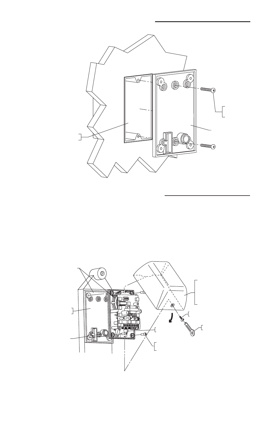
SINGLE GANG
ELECTRICAL BOX
19062 SCREW
#6-32 x 1 1/2 in.
(2) PROVIDED
BASE PLATE
O
05050- LENS COLORS
A - AMBER
B - BLUE
G - GREEN
R - RED
W - WHITE
19002 SCREW
#8-32 x 3/8 in.
(4) PROVIDED
05000 ELECTRONICS
INSTALLED
BASE PLATE
WIRE ACCESS HOLE
19016 TAMPER-PROOF
TOOL (1) PROVIDED
19011 TAMPER-PROOF
SCREW
ROUTE WIRES
THRU HOLE
STEP 6 - E
LECTRONICS
F
INAL
A
SSEMBLY
C) T
O
S
INGLE
G
ANG
E
LECTRICAL
B
OX
Wiring: After mounting circuit board assembly, connect wires. Refer to terminal strip connections (step 4).
Lens installation: Slide lip of lens behind circuit board mounting plate. Rotate lens into position. Secure with
tamperproof screw and special wrench.