Installation of alarm, Step 1 - mounting options, Installation of cabinet – STI 7555 User Manual
Page 4: Ount, Late or into, All without, Lectrical
- 4 -
STEP 1 - MOUNTING OPTIONS
INSTALLATION OF ALARM
O
DRILL
3-/16 DIA HOLES
19018 ANCHOR
#8-10
(2) PROVIDED
19039 SCREW
#6 x 1 1/4 in.
(2) PROVIDED
BASE PLATE
18074 SWITCH LOCK
SUB-SA505 KEY SWITCH
MOUNTING BRACKET
3 9/32 in.
18075 REPLACEMENT
#801 KEY
O
T
O
K
EY
M
OUNT
P
LATE OR INTO
W
ALL WITHOUT
E
LECTRICAL
B
OX
ENCLOSURE
ROUTE THE TWO KEY
SWITCH WIRES THROUGH
THE HOLE AS SHOWN
WIRE ACCESS HOLE
ROUTE THE TWO REED
SWITCH WIRES FROM
CABINET THROUGH THE
HOLE AS SHOWN
E
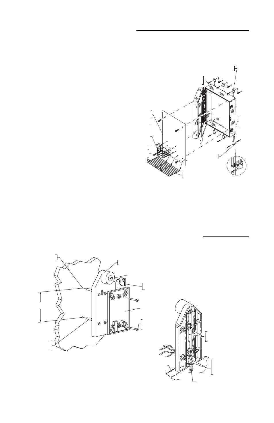
INSTALLATION OF CABINET
Note: Installation of cabinet should be before installation of alarm
because the mounting bracket butts up to cabinet.
1. Insert the (4 or 6) mounting tabs fully
into backbox mounting tab slots. Use
rubber mallet if necessary.
2. After selecting a suitable location,
place cabinet in closed position,
against the wall. Mark and
drill (4 or 6) 1/4 in.
diameter holes. Insert the
(4 or 6) 19033 anchors.
Mount cabinet by
driving in the four or six
#10 x 1 1/2 in. screws.
3. For AED model install shelf, close
and lock cabinet.
04876
MOUNTING
PLATE
OPTIONAL
TAB
MOUNTING
LOCATION
19033 ANCHOR
(6) PROVIDED
19002 SCREW
#8-32 x 3/8 in.
(4) PROVIDED
6297550
GASKET
19013 SCREW
#10 x 1 1/2 in.
(6) PROVIDED
06298 MOUNTING TABS
(6) PROVIDED
07550WR WIRE
SHELF ON AED
MODELS (ADJUSTABLE)
ROTARY ACTION
LATCH (2) PROVIDED
SHOWN WITH
COVER CLOSED
07551WR WIRE RACK
(INCLUDED WITH
AED MODEL)
19002 #8-32 x 3/8 in.
SCREWS AND (4) 19055
#8-32 KEPS NUTS PROVIDED