Icl-fr – Renkus-Heinz ICL-FR User Manual
Page 6
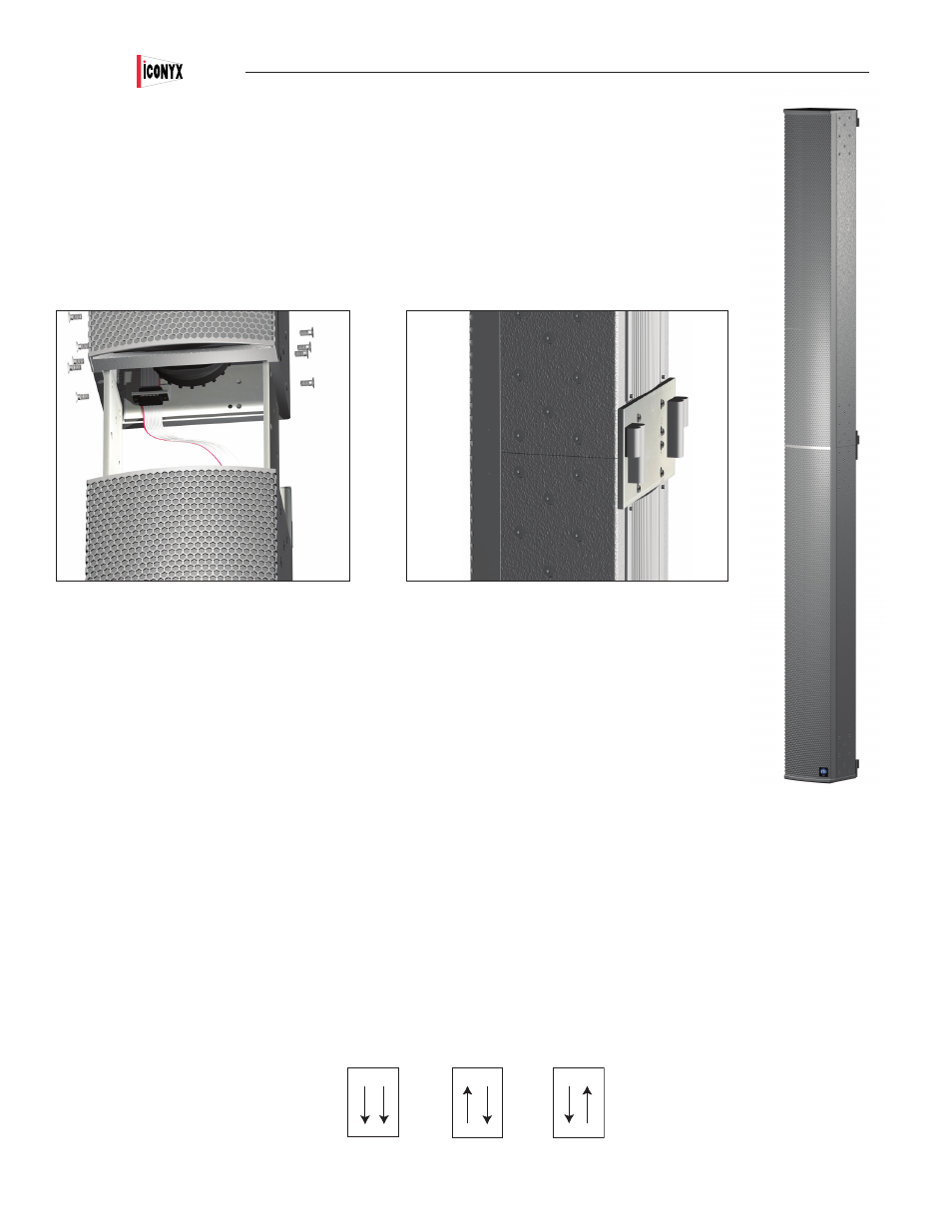
Align the two modules to be joined so that the top of the lower one and the bottom of the upper one are close to one
another, say 4” (10 cm) apart.
Insert the free end of the short ribbon cable into the socket on the second module. Using a small Phillips screw driver,
secure the connector with two 4-40 Phillips head screws (supplied). Make sure the connectors are fully seated. If neces-
sary, use a flashlight to check because if the connectors are not seated properly, you may have to disassemble the column
in order to seat them correctly.
Align the two modules and slide them together, making sure the holes in the heavy joining plates align with the holes in the
modules. Install the remaining screws into the joining plates and tighten all the screws. The assembly is now complete.
If you are making a triple array, repeat the procedure to join the ICL-FR-LM module to the other two modules.
Address Number Verification
All that remains is to verify that the Master and Slave modules are properly identified. This is accomplished with the Mas-
ter/Slave dip switches located on the input panels. See page 55 for a detailed view of an input panel. The settings were set
at the factory, but it’s always a good idea to check the settings.
Normally the bottom module will be the Master and the other modules will be the Slaves numbered 1 & 2 in ascending
order. However, as long as the switches are set properly any module can be designated as the Master. You may, for
example, designate the top module as the Master to allow you to bring the signal cables into the top of the array. Set the
switches in accordance with the drawing shown below. On single ICL-FR arrays the dip switches should always be set to the Master setting
(“00”).
Be aware that certain functions will be disabled on the Slave modules as their control has been turned over to the Master module. Preset Up,
Preset Down, Preset Enter , Input Pad, Volume Up & Volume Down, AES/EBU Input and Mute functions are all controlled only by the controls
on the Master module. Signal cables must be brought into the Master module. AC power is brought into each module.
Note that if you connected power to the Array before setting the dip switches, you will need to disconnect it and reconnect it before the dip
switch settings will take effect.
Users Manual
ICL-FR
6
MASTER
SLAVE
MASTER
SLAVE
MASTER
SLAVE
Setting
for
Master
Setting
for
Slave #1
Setting
for
Slave #2