Icl-fr – Renkus-Heinz ICL-FR User Manual
Page 53
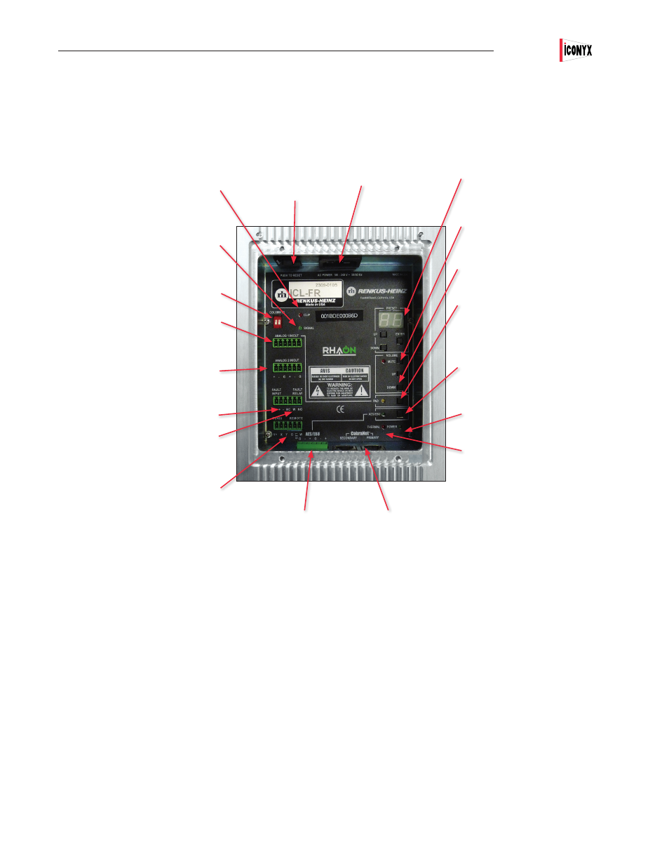
Appendix III: ICONYX ICL-FR Hardware Inputs, Outputs & Indicators, Dimensions
To connect an ICl-FR array to the RHAON network, you first make the hardware connections, and then (if you are using CobraNet for
digital audio distribution) assign signal routing using RHAON software. Since all Ethernet connections are made using RJ45 connectors
and Cat5 cable, the network infrastructure is cost-effective and easy to install. You can also connect Serial Digital (AES3 aka AES/EBU)
and analog audio to an ICL-FR array, as well as Fault Detect and Fault Relay lines.
53
Primary & Secondary Ethernet Inputs
RJ-45 female;when both are connected, change-
over to Secondary is automatic if Primary fails.
Yellow LED flashes when the connector is active,
glows steadily when data is streaming. Green LEDs
glow when connected but inactive, turn Orange to
indicate a faulty connection.
Overdrive LED
Flashes red when the Primary Analog Input
preamplifier is being overdriven
Signal LED
Flickers when an audio signal of at least -30
dBu is present at the primary analog audio
input.
Master/Slave Setup Switches
Primary Analog Input/Output
Phoenix 6-pin connector-
Secondary Analog Input/Output
Can be configured for “priority override”
Fault Input
Pins + and -; see Fault Input below for details
Fault Relay
Pins NC, W and NO; see Fault Relay below
for details
Remote Control Connections
for remote control from RS485 devices and
for preset control using rotary switches.
Pins X & Y are fora balanced RS485 Input,
Pin G is ground. Pins G, LED & W are used
for rotary switch connections. See page 52 for
details.
Fault Input
Opto-isolated input used to monitor the pres-
ence of an external wiring loop; absence of a
voltage is reported to the DSP and transmitted
to the monitoring computer over the Ethernet.
Operates on 5 to 24 V DC
Fault Relay
NO / NC relay contacts used to report a failure
to an external monitoring system; used mainly
to trigger a failure indication on a hard-wired
monitoring device; handles up to 0.5 Amps at
24 V AC or DC
Looping AES/EBU Input
and Looping Output
Preset Controls & Readout
Mute Button
Push Button Volume Controls
Also function as a manual Standby/On
control
Input Pad & LED Indicator
On / Off 10 dB pad for Primary Analog
Input; allows input signals of up to +24
dBu when inserted
AES/EBU Input Switch
When On, turns analog input 1 into an
AES/EBU input
Power LED
Glows when amplifier power is On
Thermal LED
Lights to indicate that an over-tempera-
ture sensor has shut down the amplifier
Push-To-Reset
Circuit Breaker
90/260 V AC
IEC Power
Connector
NOTE:
1. To prevent inadvertent operation the Mute, Volume Up & Volume Down, Input Pad and AES/EBU push buttons need to be pressed and
held down for several seconds before they activate.
2. In multi-module arrays, AC power for the array can be brought into any of the input ports; Signal cables must terminate in the input
port of the designated “Master” module.
3. IC Live ICL-FR arrays include Power On/Standby control, but do not have an AC Mains power switch. Pressing the Volume Up and
Volume Down push buttons simultaneously for several seconds will toggle the array between “On” and “Standby”
Users Manual
ICL-FR