Wiring, Wiring diagrams, Fuses – Stuart Turner Boostamatic2/T12-2 User Manual
Page 12
- 12 -
Cont ...
Wiring
The Wires in the mains lead (supply cord) are coloured in accordance with the following
code:
Green and Yellow: Earth
Blue: Neutral
Brown: Live
As colours of the core in the new mains lead may not correspond with the coloured
markings identifying the terminals in your connection unit, proceed as follows:
The wire which is coloured Green and yellow must be connected to the terminal marked
with the letter ‘E’ or by the earth symbol
or coloured green or green and yellow.
The wire which is coloured Blue must be connected to the terminal marked with the letter
‘N’ or coloured black.
The wire which is coloured Brown must be connected to the terminal marked with the
letter ‘L’ or coloured red.
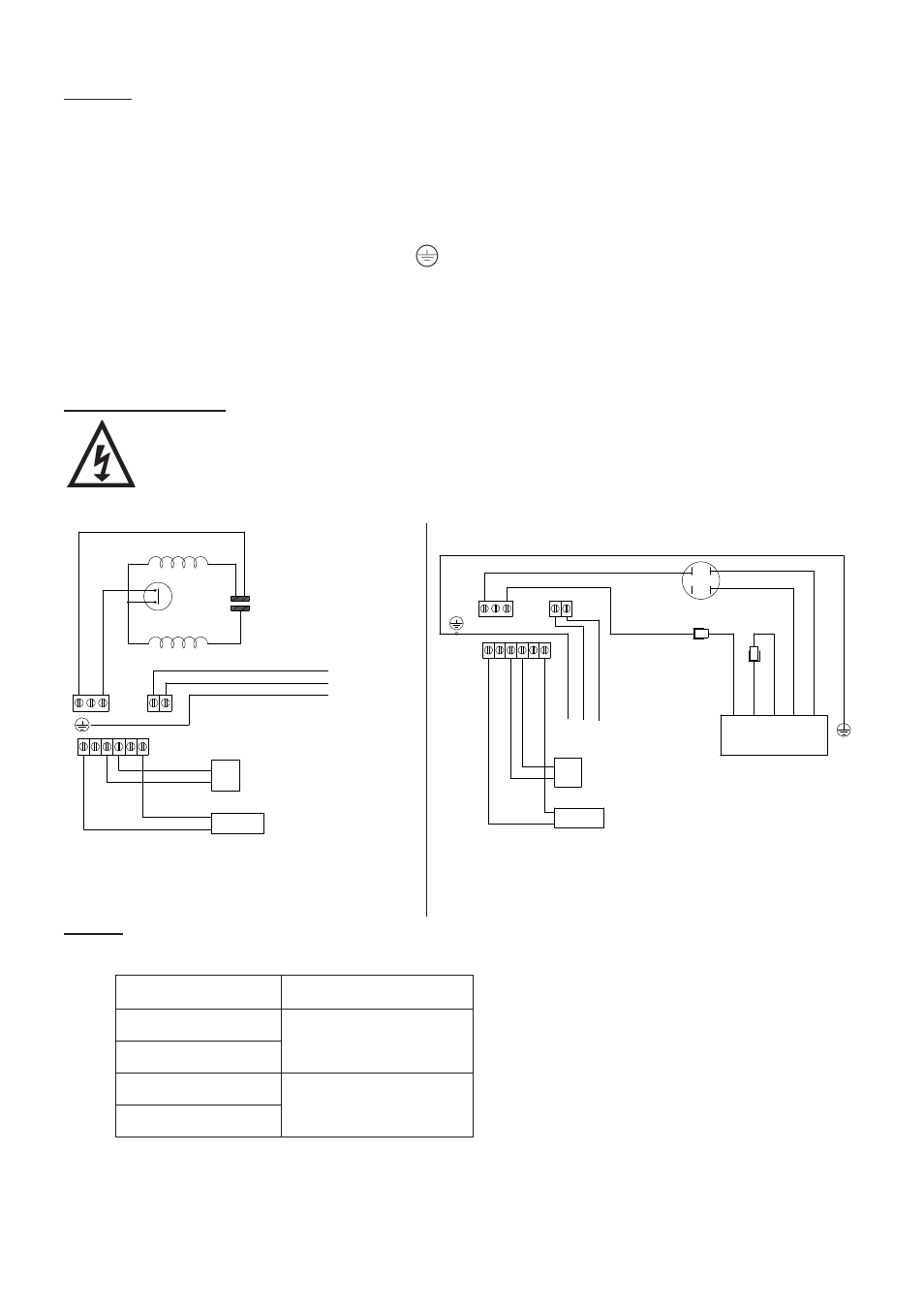
Wiring Diagrams
The supply cord and internal wiring within the terminal box are routed and
secured to ensure compliance with the electrical standard EN 60335-1. It
is essential that any disturbance of this internal wiring is avoided and the
factory routing and securing of all internal wiring is always maintained.
Fuses
The following fuse size should be used with the appropriate pump:
Model
Fuse Size (AMPS)
4000, 6000
5
K7-2
L5-4S, L7-4S
13
T6-2, T12-2
MAIN WINDING
THERMOTRIP
CAPACITOR
START WINDING
LINK WIRE
BROWN
BLACK
GREEN/
YELLOW
BLUE
BROWN
L
M
A
N
N
S2 S3 S3 S2
L
E
N
FLOWSWITCH
REED (S3)
S1
S1
PRESSURE
SWITCH (S1)
230 VAC/1PH/50Hz
SUPPLY
BLUE
N
A
M
E
GREEN/YELL
OW
BROWN
BLUE
GREEN/YELLOW
CAPACITOR
MOTOR
BLACK
BLACK
BROWN
WHITE
BLUE
N
S2 S3 S3 S2
L
FLOWSWITCH
REED (S3)
S1
S1
PRESSURE
SWITCH (S1)
L
N
BROWN
BLUE
230 VAC/1PH/50Hz SUPPLY
Fig. 14
Fig. 15
4000, 6000, K7-2
L5-4S, L7-4S,
T6-2, T12-2