Stuart Turner CH 4-30 B User Manual
Page 14
- 14 -
Cont ...
5 MAINTENANCE
5.11 Turn off water supplies to the pump and release pressure by
opening water outlets before attempting maintenance.
5.12
Pressure vessel: The pressure vessel should be checked once every 6 months
to have its air charge checked or replenished, this should be carried out
as
follows:-
a) Isolate pump electrically.
b) Isolate the water supply by closing the appropriate isolating valves.
c) Release system water pressure by opening a system outlet on the system.
d) Remove pressure vessel from the pump taking care to collect or absorb any
residual water using towels.
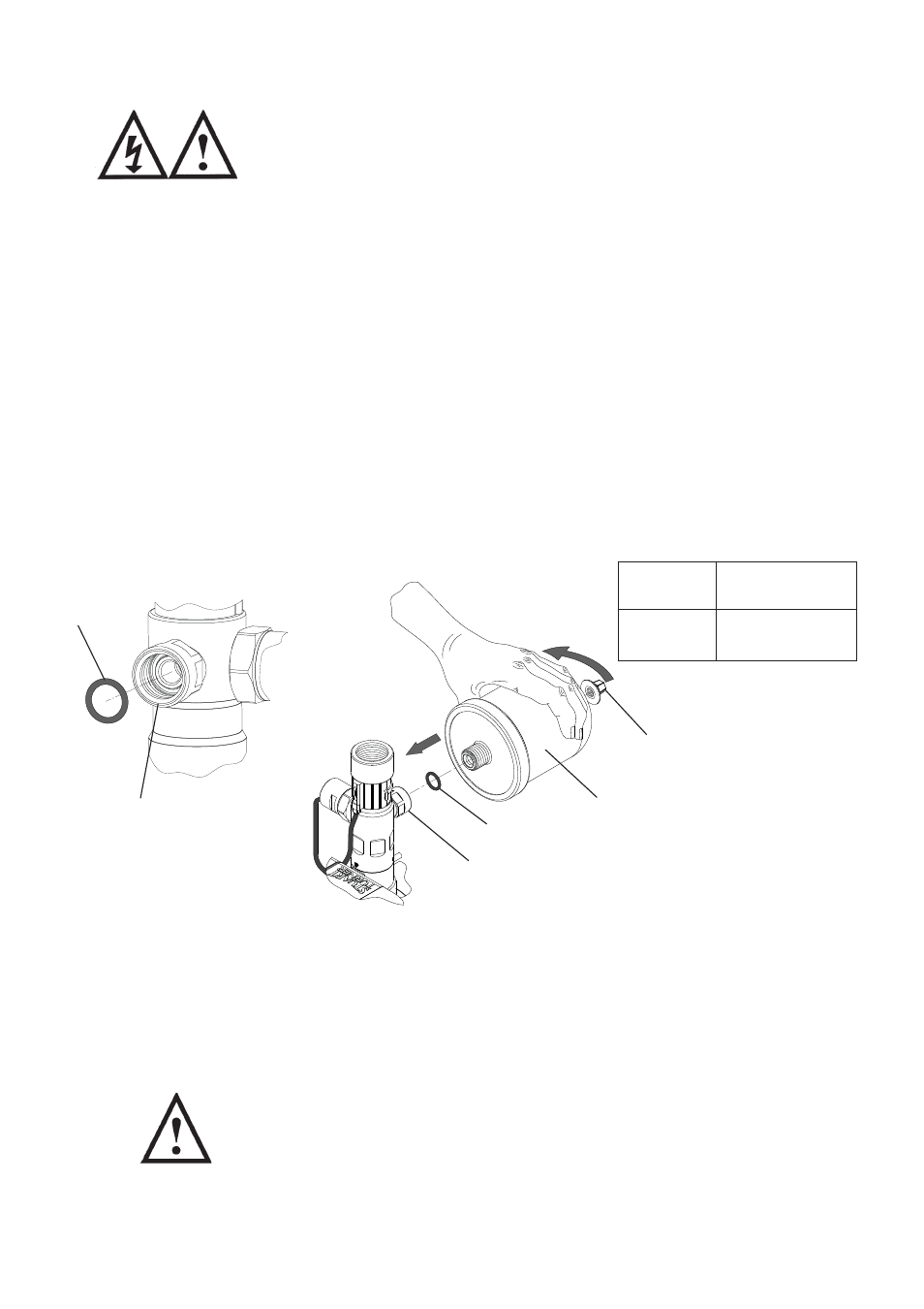
e) Check air charge at Schrader valve (Fig. 12) using a tyre pressure gauge.
f) Replenish air charge if required by injecting air into the vessel via the
Schrader valve using a car or bicycle pump (Fig. 12).
g) Reassemble pressure vessel to pump hand tight to achieve a water tight
connection. Ensure sealing ‘O’-ring is in place.
h) Close all system outlets, open inlet and outlet isolating valves.
i) After maintenance is completed refer to Section 4 - Commissioning for
instructions on re-starting pump.
5.13
Water scale: As water is heated scale deposits are released in areas of hard
water, scale can cause the mechanical seal to stick if left without use for long
periods. The pump must be run for at least 5 minutes every four weeks to
“exercise” all working parts. Run on cool water. See Section 6 - Technical
Specification for note on water temperature. This particularly applies to guest
bathrooms used infrequently.
5.14
Cleaners, Disinfectants and Descalents:
Acid based descalents and aggressive cleaning agents must not
come into contact with the pump. The pump must be removed from
the system prior to the use of these products. The system should be
flushed to remove all chemicals before the pump is re-connected.
If in any doubt as to the suitability of the chemical solutions, please
contact our PumpAssist helpline on 0844 98 000 97.
Fig. 12
Detail view of
‘O’-Ring groove
in fitting point
‘O’-Ring
Schrader valve
(under cap)
Pressure vessel
‘O’-Ring
Fitting point
Model
Air Charge
bar (psi)
All other
models
2.1 (30)
NOTE: Do not over tighten pressure vessel.