Sterling VS User Manual
Page 19
19
PIPING
To provide proper coil operation, follow all piping
recommendations listed in this manual.
Threaded pipe headers are provided on all Vertical Units
for piping connections. See Figure 5. Connections are
given in Figures 3 and 4 and Tables 1 and 2.
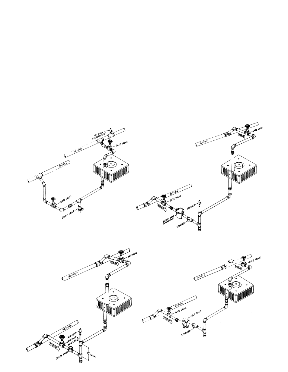
Follow standard practices and codes when installing
the piping. Provide swing joints for expansion purposes,
unions and shut-off valves for servicing purposes and
as illustrated in Figures 6 through 9, valves and traps for
control purposes. Use 45 degree angle run-offs from all
supply and return mains.
Dirt pockets should be the same pipe size as the return
tapping of the unit heater. Also, pipe size in the branch-
off should be the same size as the tapping in the traps.
Beyond the trap, the return lateral pipe should be
increased one size up to the return main.
Properly support all piping to unit! Do not allow piping
to place a strain on the coil or unit. Noise or coil failure
may occur.
It is assumed that the type of system to be used has
been selected by design engineer. The sketches shown
are for different type of steam systems or hot water
systems. For sizing of piping, traps, fi lter, etc., consult
ASHRAE guides of the manufacturer’s literature on
these products.
Figure 6 – Forced Hot Water
Figure 7 – High Pressure Steam
Figure 8 – Low Pressure Steam (Gravity)
Figure 9 – Low Pressure Vapor or Vacuum