Sterling VS User Manual
Page 18
18
D
ft (m)
25.0
(7.6)
29.0
(8.8)
31.0
(9.4)
35.0
(10.7)
38.0
(11.6)
44.0
(13.4)
48.0
(14.6)
53.0
(16.2)
55.0
(16.8)
60.0
(18.3)
66.0
(20.1)
71.0
(21.6)
76.0
(23.2)
78.0
(23.8)
87.0
(26.5)
H
ft (m)
11.0
(3.4)
12.0
(3.7)
15.0
(4.6)
14.0
(4.3)
16.0
(4.9)
15.5
(4.7)
18.0
(5.5)
21.0
(6.4)
19.0
(5.8)
21.0
(6.4)
24.0
(7.3)
28.0
(8.5)
30.0
(9.1)
34.0
(10.4)
38.0
(11.6)
D
ft (m)
20.0
(6.1)
24.0
(7.3)
26.0
(7.9)
31.0
(9.4)
33.0
(10.1)
39.0
(11.9)
42.0
(12.8)
45.0
(13.7)
47.0
(14.3)
50.0
(15.2)
55.0
(16.8)
59.0
(18.0)
65.0
(19.8)
70.0
(21.3)
75.0
(22.9)
H
ft (m)
9.0
(2.7)
10.0
(3.0)
12.5
(3.8)
11.0
(3.4)
13.0
(4.0)
12.0
(3.7)
13.0
(4.0)
14.0
(4.3)
13.0
(4.0)
15.0
(4.6)
18.0
(5.5)
20.0
(6.1)
24.0
(7.3)
26.0
(7.9)
28.0
(8.5)
D
ft (m)
16.0
(4.9)
19.0
(5.8)
23.0
(7.0)
26.0
(7.9)
29.0
(8.8)
30.0
(9.1)
31.0
(9.4)
35.0
(10.7)
38.0
(11.6)
40.0
(12.2)
47.0
(14.3)
52.0
(15.8)
57.0
(17.4)
60.0
(18.3)
63.0
(19.2)
H
ft (m)
14.5
(4.4)
19.0
(5.8)
22.0
(6.7)
21.5
(6.6)
26.0
(7.9)
22.5
(6.9)
27.5
(8.4)
31.5
(9.6)
29.5
(9.0)
32.0
(9.8)
36.0
(11.00
41.0
(12.5)
43.5
(13.3)
46.5
(14.2)
53.0
(16.2)
D
ft (m)
11.0
(3.4)
12.0
(3.7)
14.0
(4.3)
18.0
(5.5)
19.0
(5.8)
20.0
(6.1)
21.0
(6.4)
25.0
(7.6)
27.0
(8.2)
29.0
(8.8)
34.0
(10.4)
39.0
(11.9)
42.0
(12.8)
45.0
(13.7)
46.0
(14.0)
H
ft (m)
12.5
(3.8)
14.5
(4.4)
18.5
(5.6)
17.0
(5.2)
19.5
(5.9)
19.0
(5.8)
22.5
(6.9)
27.5
(8.4)
25.0
(7.6)
26.0
(7.9)
30.0
(9.1)
35.5
(10.8)
36.5
(11.1)
42.5
(13.0)
48.0
(14.6)
Unit
Size
40
62
77
104
125
144
164
200
237
285
317
367
495
585
700
Standard
Low Output
Standard
Low Output
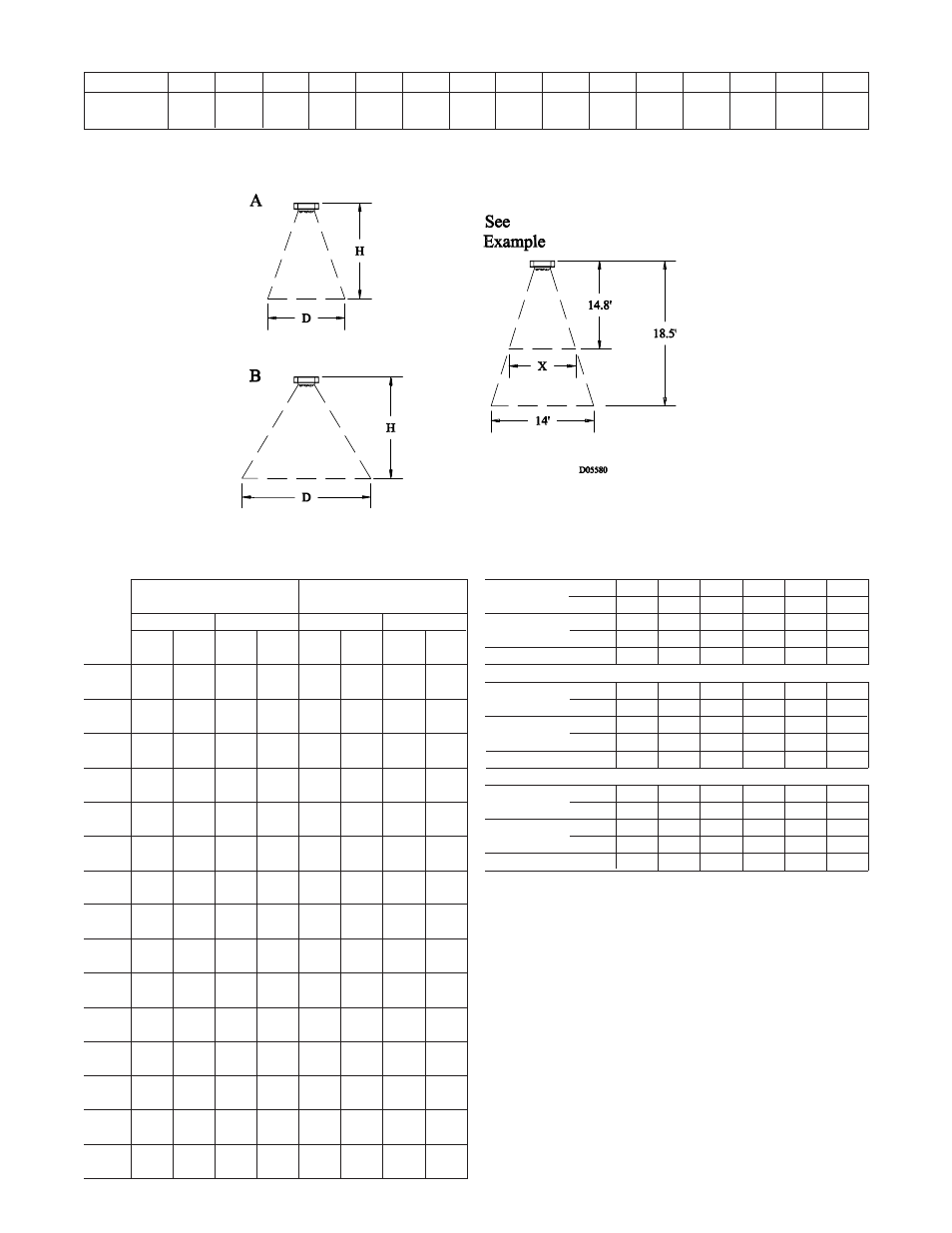
Diffuser Cone 90°
See Figure 5A
Diffuser Cone 45°
See Figure 5B
Table 19 - Mounting Height Correction Factors
150 160 170 180 190 200
(66) (71) (77) (82) (88) (93)
— — — — — —
— — — — — —
1.32 1.27 1.23 1.18 1.14 1.09
210 219 227 239 250 259
(99) (104) (108) (115) (121) (126)
— 2 5 10 15 20
— (13.8) (34.5) (68.9) (103.4)
(137.9)
1.05 1.00 0.97 0.94 0.89 0.86
267 280 287 298 307 320
(131) (138) (142) (148) (153) (160)
25 35 40 50 60 75
(172.4) (241.3) (275.8) (344.7) (413.6) (517.1)
0.83 0.80 0.76 0.73 0.70 0.69
CF = Correction Factors.
To meet OSHA requirements, units mounted lower than 8 feet from the
fl oor must be equipped with an OSHA fan guard.
Water
°F
Temperature (°C)
Steam
PSI
Pressure
(kPa)
Correction Factor
Water
°F
Temperature
(°C)
Steam
PSI
Pressure (kPa)
Correction Factor
Water
°F
Temperature (C°)
Steam
PSI
Pressure (kPa)
Correction Factor
700
60
(18.3)
Unit Size
Spread
ft (m)
Table 17 - Maximum Spread
40
15
(4.6)
62
17
(5.2)
77
20
(6.1)
104
24
(7.3)
125
26
(7.9)
144
27
(8.2)
164
28
(8.5)
200
32
(9.8)
237
35
(10.7)
285
37
(11.3)
317
45
(13.7)
495
54
(16.5)
367
50
(15.2)
585
57
(17.4)
Figure 5
Note: The “spread” is the diameter of the comfort zone at fl oor level. The above table represents the spread for standard units without a louver
cone diffuser and mounted at its maximum height at 2 PSI (13.8 kPa) steam pressure and 60°F (16*C) entering air. (See Table 16 for maximum
mounting heights.)
Table 18 - Maximum Mounting Height and Diameter
at Floor (Based on 60°F EAT and 219°F
EWT or 2 PSI steam)