Caution – Yokogawa PC-Based MX100 User Manual
Page 9
9
IM MX100-72E
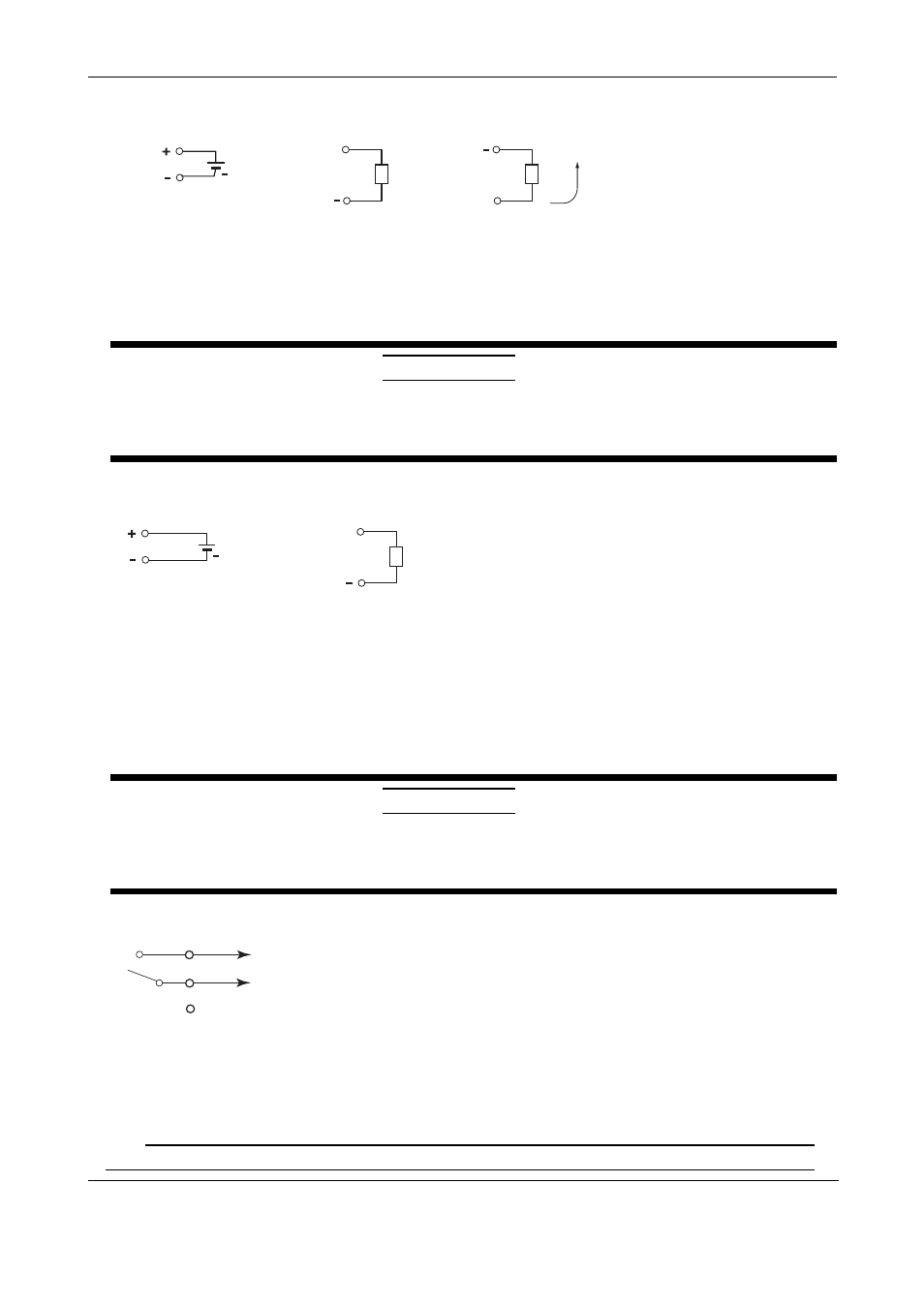
• Wiring the Analog Output Modules
External power supply
Voltage
V+
Load
+ 24 V
power supply
(when using current output)
Direction of
current
Vext
Current
I+
Load
Main Output Specifications
Terminal type:
Clamp, attached and removed in units of 4 channels
Load impedance:
Voltage 5 kΩ or more
Current 600 Ω or less
Applicable wire size:
0.08 to 2.5 mm
2
(AWG28 to 12)
CAUTION
Two power supply terminals are connected internally. Therefore, do not connect a separate external power
supply to them as fire can result. If external power is connected to one power supply terminal, use the other
power supply terminal for connection with another analog output module.
• Wiring the PWM Output Modules
External power supply
Pulse width output
V+
Load
+
4-28 V
power supply
Main Output Specifications
Output capacity:
1A/ch max, however, 4 A or less total for all modules
*1, *2
Terminal type:
Clamp, attached and removed in units of 4 channels
Applicable wire size:
0.08 to 2.5 mm
2
(AWG28 to 12)
*1 A 1A current limit circuit is built in to the output circuit. Once the current limit circuit is ON, the
circuit continues to operate unless the external power supply is turned OFF.
*2 This module has a built-in fuse. The built-in fuse protects against fires or abnormal emissions
of heat due to load short-circuiting or other abnormalities.
CAUTION
Two power supply terminals are connected internally. Therefore, do not connect a separate external power
supply to them as fire can result. If external power is connected to one power supply terminal, use the other
power supply terminal for connection with another PWM output module.
• Wiring the Digital Output Modules
C
NO
250 VDC/0.1 A, 250 VAC/2 A, or
30 VDC/2 A (resistance load)
Main Output Specifications
Contact mode:
A contact (SPST)
Contact capacity:
250 VDC/0.1 A, 250 VAC/2 A, or 30 VDC/2 A (resistance load)
Terminal type:
Clamp, attached and removed in units of 5 channels
Applicable wire size:
0.08 to 2.5 mm
2
(AWG28 to 12)
Note
Do not connect anything to the unassigned terminals of the digital output module.
5. Wiring Procedure