3 installing the holder, 4 adjusting the protection cage, Fig. 5: protection cage fig. 6: symbol – Yokogawa Pneumatic Retractables RF20H User Manual
Page 9: 4 installation
IM 12B06K05-E-E
9
4. Installation
4.1 Preparing the system
Ensure that
• Sufficient working space for operation of
the retractable holder is available.
• The process is shut off.
• Tank and tubing are pressure-free, empty
and clean.
• Connection flange and process
connection of the retractable holder fit
together.
• The process seal is positioned on the
connection flange.
• Ensure that there is no potentially
explosive atmosphere
4.2 Preparing the holder
The holder must be in the “service”
position!
• The insertion rod (process end) is completely
inserted in the cleaning chamber.
Fig. 4: “service” position
4.3 Installing the holder
Prior to installation, ensure this:
• The system is prepared (chapter 4.1).
• The holder is prepared (chapter 4.2).
How to install the holder:
• Position retractable holder on process
seal.
• Tighten process connection.
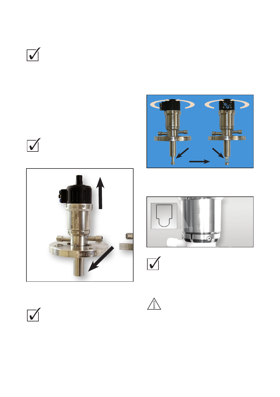
4.4 Adjusting the protection cage
A protection cage is fitted to the lower end of the
insertion rod and can be adjusted with the flow
direction. The symbol on the drive unit cylinder
indicates the position of the opening in the insertion
rod. If the symbol is parallel to the flow direction the
insertion rod is fully flown through. If the symbols
are vertical to the flow the sensor is fully protected
from direct flow. The insertion rod can be adjusted
in any intermediate position.
A) Sensor maximally streamed
B) Sensor minimally streamed
Fig. 5: Protection cage
Fig. 6: Symbol
Ensure that:
• The process is shut off.
• Tank piping and tubing are pressure-free,
empty and clean.
• There is no potentially explosive atmosphere
Leakage of process liquid when
housing cramp is opened during
running process!
Burns or tissue destruction depending on
process liquid property.
• Stop process!
• Tanks and tubing must be pressure-free!
How to adjust the protection cage:
• Loosen screws of lower housing cramp.
• Rotate drive unit and adjust symbol in flow direction.
• Tighten screws of lower housing cramp.
CAUTION!
DANGER!
WARNING!
CAUTION!
DANGER!
WARNING!
CAUTION!
DANGER!
WARNING!
CAUTION!
DANGER!
WARNING!
CAUTION!
DANGER!
WARNING!
A
B
flow direction
4 Installation
14
4.3
Installing the holder
Prior to installation, ensure the following:
"
The system is prepared (chapter 4.1).
"
The holder is prepared (chapter 4.2).
How to install the holder:
1.
Position retractable holder on process seal.
2.
Tighten process connection.
4.4
Adjusting the protection cage
A protection cage is fitted to the lower end of the insertion rod
and can be adjusted with the flow direction. The symbol on the
drive unit cylinder indicates the position of the opening in the
insertion rod. If the symbol is parallel to the flow direction the
insertion rod is fully flown through. If the symbols are vertical to
the flow the sensor is fully protected from direct flow. The
insertion rod can be adjusted in any intermediate position.
A
Sensor maximally streamed
B
Sensor minimally streamed
Fig. 5: Protection cage
Fig. 6: Symbol