7 removing the insertion rod, 8 installing the insertion rod – Yokogawa Pneumatic Retractables RF20H User Manual
Page 15
IM 12B06K05-E-E
15
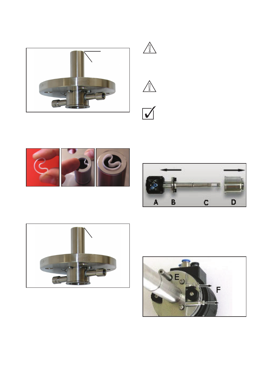
4) Remove PTFE scraper “E” on cleaning chamber
5) Remove and replace O ring “F”.
6) Position PTFE scraper “E” on O ring “F”.
Fig. 15: O rings/scraper on cleaning chamber
Scraper ø in [mm] E 19 x 6 x 1
O ring ø in [mm] F 21.89 x 2.62
Remove the PTFE scraper (E) as follows:
Only applicable for RF20H (Extract 810 and 820)
811/812 with separated cleaning chamber:
7) Separated cleaning chamber: Remove and
replace O ring “G”.
Fig. 16: Cleaning chamber 811/821
O ring ø in [mm] G 30 x 1.5
6.7 Removing the insertion rod
System is under pressure.
Process liquid will leak when holder
is disconnected from process in an
inappropriate way.
• Ensure that system is pressure-free before
removing the insertion rod.
• Drain and clean tubing or tanks.
Emitted compressed air
can cause material damage or personal injury.
• Switch off compressed air supply before
removing the pneumatic tubes.
How to remove the insertion rod from
the drive unit:
1) Remove cleaning chamber and process
connection (chap. 6.5).
2) Remove outer O rings on insertion rod
(Fig. 13: “A” and “B”).
3) Remove top housing cramp screws.
4) Remove cylinder “D” from cylinder
extension “A” (Fig. 17)
Fig. 17: Removing the cylinder
A Cylinder extension
B Piston
C Insertion rod
D Cylinder
5) Loosen screws “E” and remove pins “F” (Fig. 18).
Fig. 18: Removing the fixing elements
E 2 x M4 x 8
F 2 x pins
6) Remove insertion rod “C” from piston “B”.
F
E
6 Servicing
28
6.
Position PTFE scraper “E” on O ring “F”.
Fig. 15: O rings/scraper on cleaning chamber
Scraper
∅ in [mm]
E 19 x 6 x 1
O ring
∅ in [mm]
F 21.89 x 2.62
Remove the PTFE scraper as follows:
Only applicable for EXtract 811/812 with separated cleaning
chamber:
7.
Separated cleaning chamber: Remove and replace O ring
“G”.
Fig. 16: Cleaning chamber 811/821
O ring
∅ in [mm]
G 30 x 1.5
!!!
F
CAUTION!
DANGER!
WARNING!
CAUTION!
DANGER!
WARNING!
CAUTION!
DANGER!
WARNING!
6 Servicing
29
6.7
Removing the insertion rod
System is under pressure.
Process liquid will leak when holder is disconnected from process
in an inappropriate way.
!
Ensure that system is pressure-free before removing the
insertion rod.
!
Drain and clean tubing or tanks.
Emitted compressed air
can cause material damage or personal injury.
!
Switch off compressed air supply before removing the
pneumatic tubes.
How to remove the insertion rod from the drive unit:
1.
Remove cleaning chamber and process connection (chap.
6.5).
2.
Remove outer O rings on insertion rod (Fig. 13: “A” and “B”).
3.
Remove top housing cramp screws.
4.
Remove cylinder “D” from cylinder extension “A” (Fig. 17)
Fig. 17: Removing the cylinder
A
Cylinder extension
B
Piston
C
Insertion rod
D
Cylinder
5.
Loosen screws “E” and remove pins “F” (Fig. 18).
DANGER!
WARNING!
6 Servicing
30
Fig. 18: Removing the fixing elements
E
2 x M4 x 8
F
2 x pins
6.
Remove insertion rod “C” from piston “B”.
6.8
Installing the insertion rod
"
The descriptions refer to Fig. 17 and Fig. 18 in chap. 6.7
Removing the insertion rod!
How to assemble the insertion rod and the drive unit:
1.
Adjust slots in insertion rod “C” to piston “B” and put
together.
2.
Insert pins “F”
3.
Tighten screws “E”.
4.
Grease inside wall of cylinder “D”.
5.
Slide cylinder “D” over insertion rod “C”.
6.
Adjust cylinder “D” to cylinder extension “A”.
7.
Squeeze until cylinder snaps into place.
8.
Bring top housing cramp in position and tighten screws.
9.
Insert O rings at insertion rod (Fig. 13: “A” and “B”).