5 v. maximum input current i, 100 ma. maximum input power p, 2 w. effective internal capacitance c – Yokogawa EXA SC202 2-Wire Conductivity Transmitter/Analyzer User Manual
Page 20: 22 nf. effective internal inductance l, 4 v. maximum output current i
IM 12D08B02-01E
Specifications 2-7
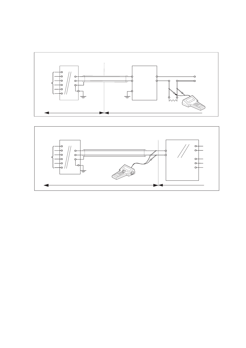
2-5. Control Drawing SC202S mA HART® Specifi cation (ATEX)
SC 202S (C onductivity/Resistivity-transmitter)
Safe area
U o = 31.5 V o lt D C
Io = 100 mA
Po = 1.2 W att
EEx ia or ib C ertified R epeater
Pow er Supply
(H AR T C ompatible)
O utput
Supply
SE N SO R (S)
term inals 11-16
+
_
G
SEN SO R (S)
term inals 11-16
H azardous area
Safe area
+
_
G
earth
earth
Intrinsically safe design
C EN ELEC standard EEx ia IIC : T4 for ambient temp. < 55°C
T6 for ambient temp. < 40°C
C ertificate nr. KEM A 06ATEX 0220 X
SC 202S
+
_
Load
R esistance
EEx ia or ib
C ertified safety barrier or pow er
w ith R int=300
:
Io = 100 mA
U o = 31.5 V o lt D C
H azardous area
+
_
24 volts D C N ominal
Supply V oltage.
Intrinsically safe design
C EN ELEC standard EEx ia IIC : T4 for ambient temp. < 55°C
T6 for ambient temp.< 40°C
C ertificate nr. KEM A 06ATEX 0220 X
(HA R T compatible)
(C onductivity/R esistivity-transmitter)
Zone 0 or 1
Zone 0 or 1
Functional
Functional
earth
Functional
・
Sensor(s) are of a passive type to be regarded as ‘simple apparatus’.
・
Electrical data of the SC202S.
- Supply and output circuit (terminals + and -):
Maximum input voltage U
i
= 31.5 V. Maximum input current I
i
= 100 mA.
Maximum input power P
i
= 1.2 W.
Effective internal capacitance
C
i
= 22 nF.
Effective internal inductance
L
i
= 35 PH.
- Sensor input circuit (terminals 11 through 16):
Maximum output voltage U
o
= 14.4 V. Maximum output current I
o
= 13 mA.
Maximum allowed external capacitance
Co = 59 nF (for SC202S-A),
Co = 2.9 uF (for SC202S-N).
Maximum allowed external inductance
Lo = 200 mH (for SC202S-A),
Lo = 450 mH (for SC202S-N).
・
Barriers and power supply specification must not exceed the maximum values as
shown in the diagram above. These safety descriptions cover most of the commonly
used industry standard barriers, isolators and power supplies.
・
The Hand Held Communicator must be of a ATEX certified intrinsically safe type in
case it is used on the intrinsically safe circuit in the hazardous area or of a ATEX
certified non-incendive type in case it is used in the non-incendive circuit in the
hazardous area.