Yokogawa EXA SC202 2-Wire Conductivity Transmitter/Analyzer User Manual
Page 102
IM 12D08B02-01E
3-14 Appendix
2/3
QIS 12D08B02-71E
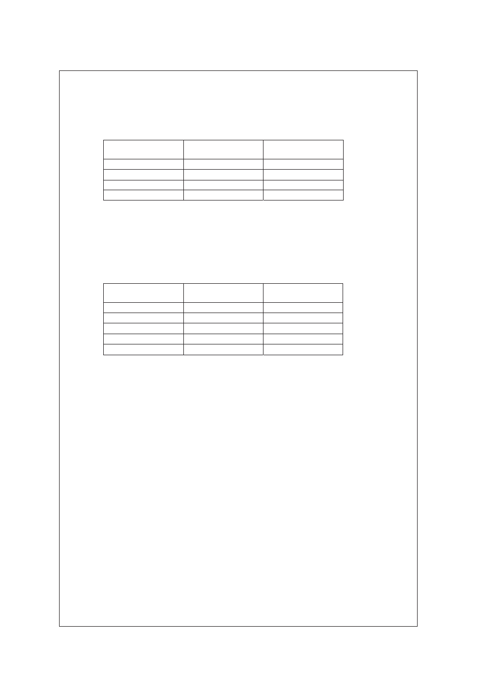
In this state, change the resistance value of the decade resistance box 1 as shown in Table 1.
The corresponding temperature indication must be within the range.
Table 1 Temperature Indication Check
Reference
Temperature
Resistance of
Resistance Box 1
Indication Range
–10 °C
960.9 :
–10
±0.3
°C
75 °C
1289.8 :
75
±0.3
°C
190 °C
1721.6 Ω
190
±0.3
°C
240 °C
1904.6 Ω
240
±0.3
°C
3.4 Conductivity Indication Check
Connect the instruments as shown in Figure 1, and set them as follows.
Decade resistance box 1:
100 Ω
Decade resistance box 2:
10 Ω
In this state, change the resistance value of the decade resistance box 2 as shown in Table 2.
The corresponding conductivity indication must be within the range.
Table 2 Conductivity Indication Check (Cell Constant : 0.1/cm)
Reference
Conductivity
Resistance of
Resistance Box 2
Indication Range
10 mS/cm
10 Ω
10
±0.05
mS/cm
1 mS/cm
100 :
1
±0.005
mS/cm
100 μS/cm
1 k:
100 ±0.5 μS/cm
10 μS/cm
10 k:
10
±0.05
μS/cm
1 μS/cm
100 k:
1
±0.005
μS/cm