2. wiring diagrams, 2-1. example of non-explosionproof system, 3. sensor wiring – Yokogawa EXA PH202 2-Wire pH/ORP Analyzer User Manual
Page 99: 2. wiring diagrams -2, 2-1. example of non-explosionproof system -2, 3. sensor wiring -2, Warning
IM 12B0702-01E
11-2 Appendix
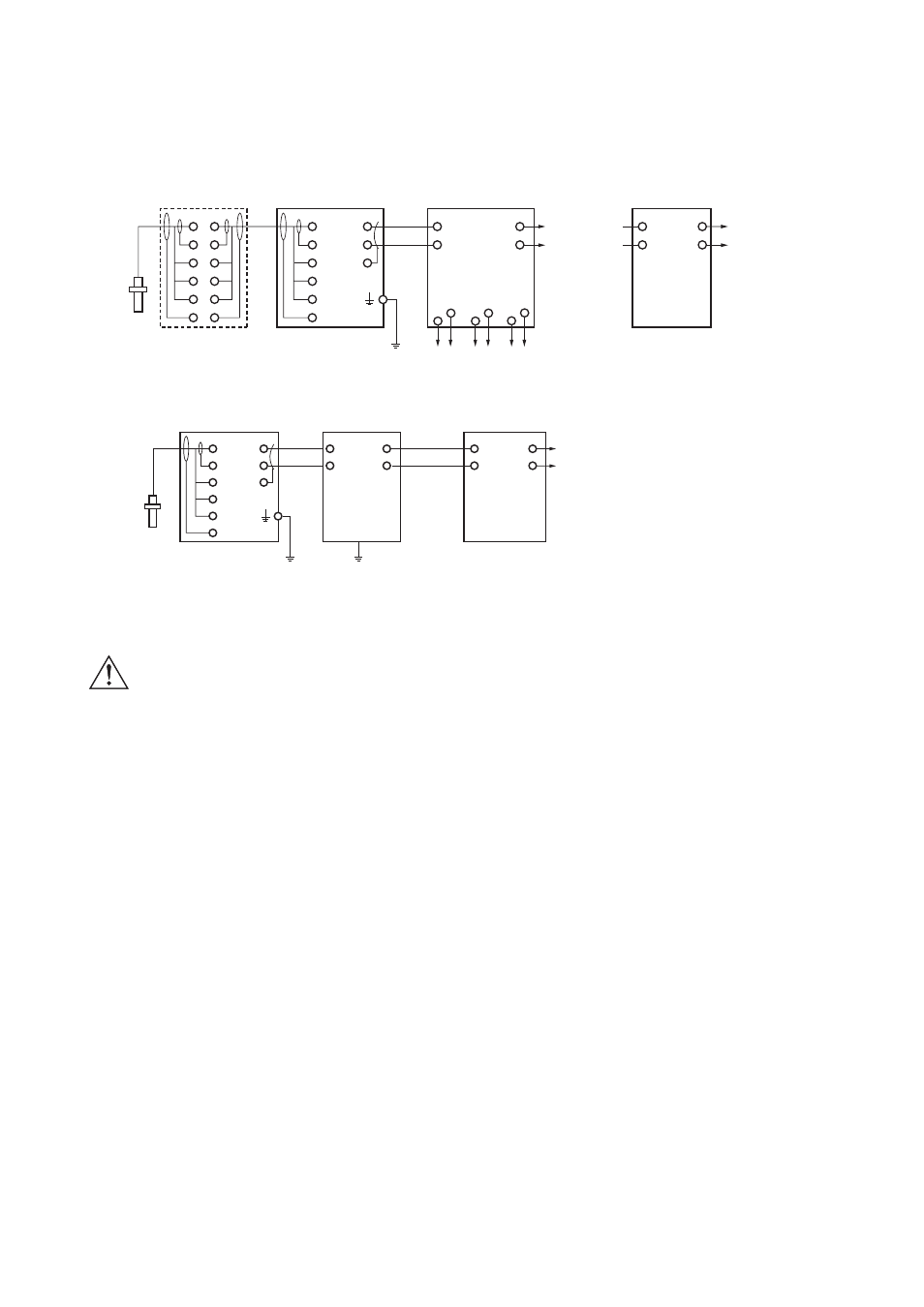
11-2. Wiring diagrams
11-2-1. Example of Non-Explosionproof System
15
PH8EFP
PH8ERP
PH8EHP
"2
WTB10
Terminal Box
PH202G
pH/ORP Transmitter
16
13
12
11
14
PH201G
Distributor
SDBT
Distributor
15
16
13
+
-
A(+)
B(-)
Output Signal
(1 to 5V DC)
Output Signal
(1 to 5V DC)
1(+)
2(-)
(+)A
(-)B
C
e
WASH
f
(CMN)D
G
12
11
14
c
FAIL
d
a
Hold
b
F2.3E.eps
(100Ω or less)
11-2-2. Example of Intrinsically Safe Explosionproof System
PH8EFP
PH8ERP
PH8EHP
PH202S
pH/ORP Transmitter
Safety Barrier
Distributor
15
16
13
+
-
Output
G
12
11
14
*1
pH/ORP
Sensor
*1: Use a 2-conductor shielded cable with an outside diameter of 6 to 12 mm. Shield must be connected to internal terminal G of transmitter
and left unconnected at the other side.
*2: Transmitter must be grounded using external terminal: for general purpose version ground resistance of PH202G should not exceed 100V
(Japanese Class D grounding) .
Ground to earth
F2.4E.eps
Use an appropriate DC power supply (such as from the PH201G distributor) for the PH202
transmitter. Under no circumstances should you connect AC power such as 100V AC or similar AC
power supply line. To measure pH or ORP in hazardous locations, use the PH202S or PH202SJ with
intrinsic safety barriers.
Grounding:
Be sure to ground the transmitter by using the ground terminal on its case.
Connect the G terminal inside the transmitter, to the shield wire of two-core shield cable which is
conneced between the distributor and transmitter.
For the PH202G transmitter (this does not apply to the PH202S) if you cannot ground the G
terminal on the transmitter case then connect this G terminal to the shield of the two-wire cable
connecting the transmitter and distributor, and ground it at the distributor end.
11-3. Sensor wiring
Refer to Figure 11-1 and 11-2, which includes drawings that outline sensor wiring.
The PH202 can be used with a wide range of commercially available sensor types, both from
Yokogawa and other manufacturers. The sensor systems from Yokogawa fall into two categories; the
ones that use a fixed cable and the ones with separate cables.
To connect sensors with fixed cables, simply match the terminal numbers in the instrument with the
identification numbers in the instrument on the cable ends.
The recommended procedure is to color-code each end of the cables to match the sensors with the
color strips provided with each cable. This provides a quick way to identify the ends of the cables
belonging to a particular sensor when they are installed.
(The procedure for fixing the identification labels is described in detail in the instruction sheet
provided with the cable.)
WARNING
WARNING