Yokogawa EXA PH202 2-Wire pH/ORP Analyzer User Manual
Page 94
IM 12B07D02-01E
10-8 Appendix
(Note):
HART protocol DD files can be downloaded by following URL.
http://www.yokogawa.com/an/download/an-dl-fieldbus-001en.htm
2. Hold fnc
1. Hold status
3. Hold type
4. Hold fix
1. T.meas
2. Man. temp
1. PV
2. Temp
3. PV % rnge
4. More pr.var
1. Status
2. Hold
3.Temp.man
4. Logbook
5. Calibrate
6. Loop test
1.Tag
2.Device information
Device setup
PV
AO1
LRV
URV
1.Process variables
2.Diag/Service
3.Basic setup
1. Slope
2. Aspot
3. Input 1 imp.
4. Input 2 imp.
Note:
“PV” means
Primary value
“AO1” means
Analog output
“LRV” means
Lower rangeval
“URV” means
Upper rangeval
1. Date
2. Descriptor
3. Message
4. Write protect
5. Manufacturer
6. Dev id
1. Logbook conf.
2. Logbook 1
3. Logbook 2
1. Sample
2. Manual Cal. PV
1. Powerup
2. Powerdwn
3. Defaults
4. Lg. Erased
5. Low range
6. High range
7. Hold on
8. Hold off
9. Error on
Error off
Temp. adj
Man.Temp
Aspot
Aspot 2
Slope
Temp. coef
Z1.(cal)
Z2.(cal)
Stab.time.
I.T.P.
Zero.pnt
New sensor
One.p cal
Two.p cal
Note:
“
PV % rnge
” means
% of output range
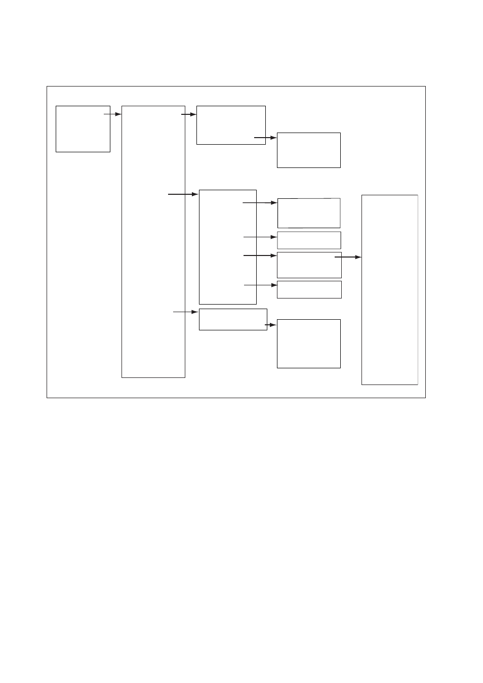
ON LINE MENU Level 1 menu
Level 2 menu
Level 3 menu
Level 4 menu
Continued next page
Menu structure for HHT 375 shown below.