2 model and suffix codes, 3 optional specifications, Model and suffix codes -5 – Yokogawa YTA320 User Manual
Page 39: Optional specifications -5
<7. General Specifications>
7-5
IM 01C50B01-01E
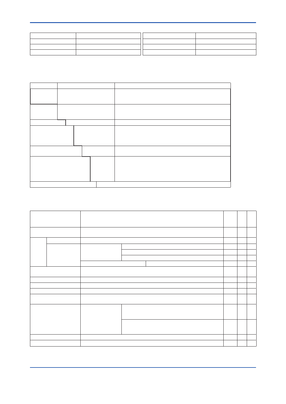
Factory setting (◊)
Tag No.
Left blank if not specified in order
Unit of calibration range
“°C” if not specified in order
Input sensor type
“Pt100, 3-wire” if not specified in order
Damping constant
2 seconds
Lower calibration range “0” if not specified in order
Sensor burnout
High side (110%, 21.6 mA DC)
*1
Upper calibration range “100” if not specified in order
Output when transmitter fails High side (110%, 21.6 mA DC)
*2
*1:
When option code C1 is specified, Low takes effect (–2.5%, 3.6 mADC).
*2:
When option code C1 is specified, Low takes effect (–5%, 3.2 mADC or less).
7.2 Model and Suffix Codes
Model
Basic Specification Codes
Description
YTA0
YTA30
YTA320
· · · · · · · · · · · · · · · · · · · · · ·
· · · · · · · · · · · · · · · · · · · · · ·
· · · · · · · · · · · · · · · · · · · · · ·
Temperature transmitter (1 input type)
High precision temperature transmitter (1 input type)
High precision temperature transmitter (2 input type)
Output
signal
-D · · · · · · · · · · · · · · · · · · · ·
-E · · · · · · · · · · · · · · · · · · · ·
-F · · · · · · · · · · · · · · · · · · · ·
4 to 20mA DC output, BRAIN communication type
4 to 20mA DC output, HART communication type
FOUNDATION Fieldbus communication type (YTA320 only)
—
A· · · · · · · · · · · · · · · · · · Always A
Electrical connection
0 · · · · · · · · · · · · · ·
2 · · · · · · · · · · · · · ·
3 · · · · · · · · · · · · · ·
4 · · · · · · · · · · · · · ·
G1/2 female
1/2 NPT female
Pg13.5 female
M20 female
Built-in indicator
D· · · · · · · · · · ·
N· · · · · · · · · · ·
Digital indicator
None
Mounting bracket
B· · · · · · ·
D· · · · · · ·
J · · · · · · ·
K· · · · · · ·
N· · · · · · ·
SUS304 Stainless steel 2-inch horizontal pipe mounting *
1
SUS304 Stainless steel 2-inch vertical pipe mounting *
1
SUS316 Stainless steel 2-inch horizontal pipe mounting
*1
SUS316 Stainless steel 2-inch vertical pipe mounting
*1
None
Additional specifications
/
Additional specifications
*1:
Use bolts for wall mounting.
7.3 Optional Specifications
Item
Descriptions
Code
YT
A
0
YT
A
3
0
YT
A
32
0
Lightning protector
Power supply voltage: 10.5 to 32 V DC
Allowable current: Max. 6000A(1×40μs), repeating 1000A(1×40μs) 100 times
A
Painting Coating change
Epoxy resin coating
X
Color change
Amplifier cover only
Munsell renotation code: NI1.5 Black
P
Munsell renotation code: 7.5BG4/1.5, Jade green
P2
Metallic silver
P7
Amplifier and Terminal covers
Munsell renotation code: 7.5R4/14 Red
PR
SUS316 exterior parts
Exterior parts on the amplifier housing (name plates, tag plate, screws)
will become SUS316 stainless steel
*3
HC
Stainless Steel Housing*
1
Housing Material: SCS14A Stainless steel
E
Wired tag plate
SUS304 stainless steel tag plate wired onto transmitter
*4
N4
Calibration Unit
Addition of Degree F and Degree R unit
D2
Output signal low-side in
Transmitter failure*
2
Output signal low-side: –5 %, 3.2 mA DC or less.
Sensor burnout is also set to ‘Low’: –2.5 %, 3.6 mA DC
C
NAMUR NE43
compliant*
2
Output signal limits:
3.8 mA to 20.5 mA
Failure alarm down-scale: output status at CPU failure and
hardware error is –5%, 3.2 mA or less.
Sensor burnout is also set to ‘Low’: –2.5%, 3.6 mA
C2
Failure alarm up-scale: output status at CPU failure and
hardware error is 110%, 21.6 mA or more.
Sensor burnout is also set to ‘High’: 110%, 21.6 mA
C3
Data Configuration*
2
Description into “Descriptor” parameter of HART protocol. (max. 16 characters)
CA
Sensor matching function*
2
RTD Sensor matching function
CM
×
*1 : Not applicable with other option codes, except for A, C1, D2 and CM1.
*2 : Not applicable for output signal code F.
*3 : This specification is not included in option code E1. Select HC for SUS316 exterior parts regardless of E1.
*4 : When HC is selected, the material is SUS316 stainless steel.