Yokogawa YTA320 User Manual
Page 18
<2. Notes on Handling>
2-2
IM 01C50B01-01E
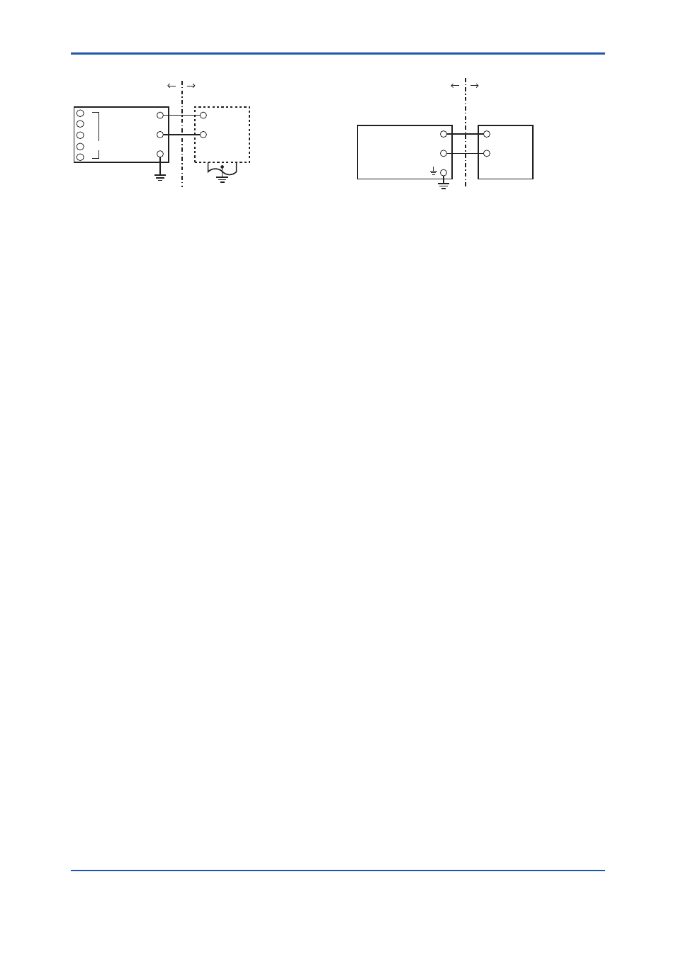
Transmitter
Supply
Safety Barrier *1
Hazardous Location
Nonhazardous Location
+
–
+
–
[Installation Diagram]
F0212.ai
Sensor
1
2
3
4
5
*1:
In any safety barriers used the output current must be
limited by a resistor “R” such that Imaxout-Uz/R.
b) IECEx Intrinsic safety “ic”
Caution for IECEx Intrinsic safety “ic”.
Note 1. Model YTA110/SU2, YTA310/SU2, and
YTA320/SU2 temperature transmitters are
applicable for use in hazardous locations:
• No. Certificate: IECEx KEM 09.0032X
• Applicable standard: IEC60079-11:2011,
IEC60079-0:2011, IEC60079-26:2006
• Type of Protection and Marking Code:
Ex ic IIC T4...T5 Gc
• Ambient Temperature:
-40 to 70°C for T4, -40 to 50°C for T5
• Enclosure: IP67
Note 2. Electrical Data
• [Supply circuit (Terminals: + and –)]
Ui = 30 V, Ci = 20 nF, Li = 730 μH
• [Sensor circuit (Terminals: 1 to 5)]
Uo = 9 V, Io = 40 mA, Po = 90 mW, Co = 0.7 μF,
Lo = 10 mH
Note 3. Installation
• All wiring shall comply with local installation
requirements. (Refer to the installation diagram)
Note 4. Operation
• Keep strictly the “WARNING” on the label on
the transmitter.
WARNING: POTENTIAL ELECTROSTATIC
CHARGING HAZARD. SEE
USER’S MANUAL BEFORE USE.
Note 5. Maintenance and Repair
• The instrument modification or parts
replacement by other than authorized
representative of Yokogawa Electric
Corporation is prohibited and will void IECEx
Certification.
Note 6. Special condition for safe use
• Avoid any actions that cause the generation of
electrostatic charge on the non-metallic parts,
such as rubbing with a dry cloth on coating face
of product.
Temperature
Transmitter
Suppry
Power Supply
Hazardous Location
(Zone 2 only)
Nonhazardous Location
+
–
+
–
[Installation Diagram]
F0213.ai
Ratings of the Power Supply are as follows:
Maximum Voltage: 30 V
c) IECEx Flameproof Type and Dust Ignition
Proof Type
Caution for IECEx flameproof type and Dust Ignition
Proof Type
Note 1. Model YTA110/SF2, YTA310/SF2, and
YTA320/SF2, YTA110/SU2, YTA310/SU2, and
YTA320/SU2 temperature transmitters are
applicable for use in hazardous locations:
• No. IECEx KEM 07.0044
• Applicable Standard: IEC 60079-0,
IEC 60079-1, IEC 61241-0, IEC 61241-1
• Type of Protection and Marking Code:
Ex d IIC T6/T5, Ex tD A21 IP67 T70°C, T90°C
• Ambient Temperature for Gas Atmospheres:
–40 to 75°C (T6), –40 to 80°C (T5)
• Ambient Temperature for Dust Atmospheres:
–40 to 65°C (T70°C), –40 to 80°C (T90°C)
• Enclosure: IP67
Note 2. Electrical Data
• Supply voltage: 42 V dc max.
• Output signal: 4 to 20 mA
Note 3. Installation
• All wiring shall comply with local installation
requirement.
• The cable entry devices shall be of a certified
flameproof type, suitable for the conditions of
use.
Note 4. Operation
• Keep strictly the “WARNING” on the label on
the transmitter.
WARNING: AFTER DE-ENERGIZING, DELAY
5 MINUTES BEFORE OPENING.
WHEN THE AMBIENT TEMP. ≥
70°C, USE THE HEATRESISTING
CABLES OF HIGHER THAN
90°C.
• Take care not to generate mechanical spark
when access to the instrument and peripheral
devices in hazardous location.