Terminals – Yokogawa YTA320 User Manual
Page 38
<7. General Specifications>
7-4
IM 01C50B01-01E
Table 7.3
YTA30, YTA320 Effect of Ambient Temperature
Sensor Type
Input Range
A/D Coefficient
D/A Coeffieicient
°C
°F
T/C
B
100
300
1000
to
to
to
300
1000
1820
212
572
1832
to
to
to
572
1832
3308
± ( 0.530°C - 0.080 % of reading)
± ( 0.350°C - 0.021 % of reading )
± ( 0.140°C)
± {0.0088% of span + 0.007%
of (reading - LRV)}
E
-200 to
1000
-328 to
1832 ± ( 0.035°C + 0.042 % of abs.reading)
J
-200
0
to
to
0
1200
-328
32
to
to
32
2192
± ( 0.039°C + 0.020 % of abs.reading)
± ( 0.039°C + 0.0029 % of reading)
K
-200
0
to
to
0
1372
-328
32
to
to
32
2502
± ( 0.046°C + 0.020 % of abs.reading)
± ( 0.046°C + 0.0054 % of reading)
N
-200
0
to
to
0
1300
-328
32
to
to
32
2372
± ( 0.054°C + 0.010 % of abs.reading)
± ( 0.054°C + 0.0036 % of reading)
R
-50
200
to
to
200
1768
-58
392
to
to
392
3214
± ( 0.210°C - 0.032 % of abs.reading)
± ( 0.150°C)
S
-50
200
to
to
200
1768
-58
392
to
to
392
3214
± ( 0.210°C - 0.032 % of abs.reading)
± ( 0.150°C)
T
-200
0
to
to
0
400
-328
32
to
to
32
752
± ( 0.046°C - 0.036 % of abs.reading)
± ( 0.046°C)
W3
0
1400
to
to
1400
2300
32
2552
to
to
2552
4172
± ( 0.100°C + 0.0040 % of reading)
± ( -0.130°C + 0.020 % of reading)
W5
0
1400
to
to
1400
2300
32
2552
to
to
2552
4172
± ( 0.100°C + 0.0040 % of reading)
± ( -0.120°C + 0.020 % of reading)
L
-200
0
to
to
0
900
-328
32
to
to
32
1652
± ( 0.039°C + 0.020 % of abs.reading)
± ( 0.039°C + 0.0029 % of reading)
U
-200
0
to
to
0
600
-328
32
to
to
32
1112
± ( 0.046°C + 0.036 % of abs.reading)
± ( 0.046°C)
RTD
Pt100
Pt200
Pt500
JPt100
Cu
-200
-200
-200
-200
-70
to
to
to
to
to
850
850
850
500
150
-328
-328
-328
-328
-94
to
to
to
to
to
1562
1562
1562
932
302
± ( 0.047°C + 0.009 % of reading)
± ( 0.065°C + 0.012 % of reading)
± ( 0.047°C + 0.009 % of reading)
± ( 0.047°C + 0.009 % of reading)
± ( 0.320°C + 0.120 % of reading)
Ni120
-70 to
320
-94 to
608 ± ( 0.016°C + 0.007 % of reading)
mV
—
± (0.001mV + 0.0043 % of abs.reading)
ohm
—
± ( 0.040Ω + 0.0088 % of reading)
Note: Temperature Effect = A/D coeffieicnt + D/A coefficient (The data in the table is the coeffcient per 10°C change.)
Example 1; Pt100Ω, 0 to 200°C calibration range, 50°C reading
(0.047°C + 50°C × 0.009%) + [200°C Ч 0.0088% + (50 - 0) Ч 0.007%]
= (0.047°C + 0.0045°C) + (0.0176°C + 0.0035°C )
= ± 0.0726°C [ per 10°C change ]
Example 2; T T/C, -100 to 100°C calibration range, 250°C reading
(0.046°C + | 250°C | × 0.036%) + {200°C Ч 0.0088% + [250 - (-100)] Ч 0.007%}
= (0.046°C + 0.018°C) + (0.0176°C + 0.0035°C )
= ± 0.0851°C [ per 10°C change ]
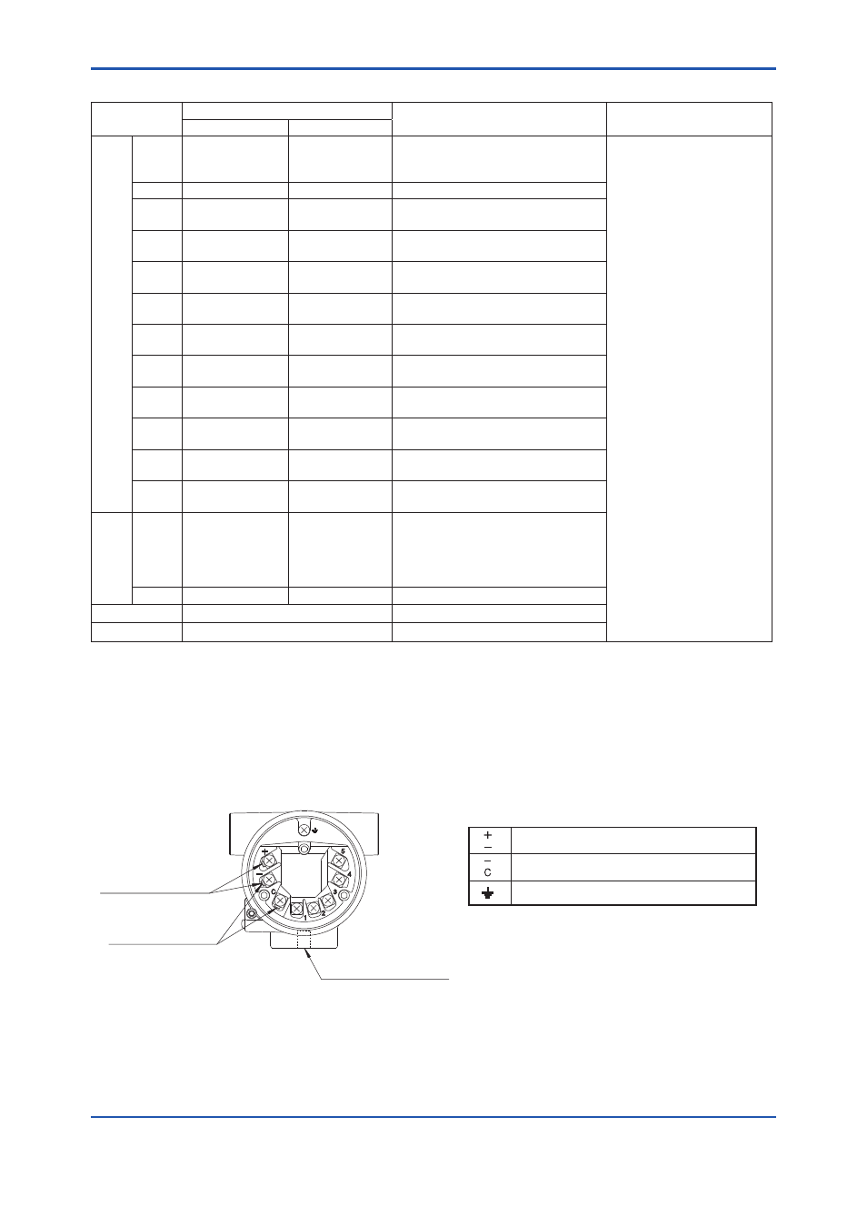
Terminals
F0702.ai
Power Supply and output terminal
External Indicator (ammeter) terminal
*1
Ground terminal
Terminal Configuration
Communication
Terminals (BT200 etc.)
Connection hook
CHECK METER
Connection hook
*1
*1: When using an external indicator or check meter,
the internal resistance must be 10Ω or less.
The hook is not available for Fieldbus
communication type(output signal code F).
M10×1.5 12-deep female
for mounting bracket