Warning – Yokogawa YTA320 User Manual
Page 14
<2. Notes on Handling>
2-8
IM 01C50B01-01E
Temperature Transmitter
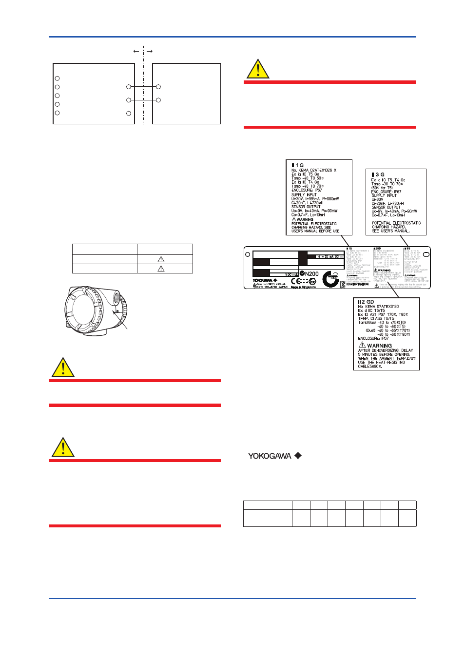
Electrical data are as follows;
Supply Input (Terminals: + and -)
Ui = 30 V
Ci = 28 nF
Li = 730 μH
Sensor Output (Terminals: 1 to 5)
Uo = 9 V
Io = 40 mA
Po = 90 mW
Co = 0.7 μF
Lo = 10 mH
SUPPLY
SUPPLY
SENSOR
Associated Apparatus
Hazardous Area
Non-hazardous Area
+
–
+
–
C
F0206.ai
1
2
3
4
5
SENSOR
(2) Electrical Connection
The type of electrical connection is stamped near
the electrical connection port according to the
following marking.
Marking
Screw Size
ISO M20×1.5 female
M
A
ANSI 1/2 NPT female
T0201.ai
F0207.ai
Location of the marking
(3)
Installation
WARNING
All wiring shall comply with local installation
requirement and local electrical code.
(4) Operation
WARNING
• OPEN CIRCUIT BEFORE REMOVING
COVER. INSTALL IN ACCORDANCE WITH
THIS USER’S MANUAL
• Take care not to generate mechanical
sparking when access to the instrument and
peripheral devices in hazardous locations.
(5) Maintenance and Repair
WARNING
The instrument modification or parts replacement
by other than authorized Representative of
Yokogawa Electric Corporation is prohibited and
will void the certification.
(6) Name Plate
F0208.ai
TEMPERATURE
TRANSMITTER
YTA
MODEL
SUFFIX
STYLE
SUPPLY
NO.
OUTPUT
CAL
RNG
*3
MODEL: Specified model code.
SUFFIX: Specified suffix code.
STYLE: Style code.
SUPPLY: Supply voltage.
NO.: Serial number and year of production*
1
.
OUTPUT: Output signal.
FACTORY CAL: Specified calibration range.
TOKYO 180-8750 JAPAN:
The manufacturer name and the address*
2
.
*1: The third figure from the left shows the production year.
The relationship between the production year and the
third figure is shown below.
The third figure
F
G
H
J
K
L
M
The year of
Production
2006 2007 2008 2009 2010 2011 2012