Technical details of modbus communication, 1 range check, 2 byte order of transmission – Yokogawa RotaMASS 3-Series User Manual
Page 63: Technical details of modbus communication -1, 1 range check -1, 2 byte order of transmission -1
IM 01R04B08-00E-E 1st edition February 15, 2012 -00
All Rights Reserved. Copyright © 2012, Rota Yokogawa
<8. TECHNICAL DETAILS OF MODBUS COMMUNICATION>
8-1
8. TECHNICAL DETAILS OF MODBUS
COMMUNICATION
8.1 Range check
According to the Modbus specification error bit and exception codes are only defined for physical
transmission errors. Therefore there is no possibility to signal logical errors like violation of data ranges or
invalid selections at the time when a register is being written.
ROTAMASS 3 Series Modbus communication type will check all values written via Modbus. Values which
are invalid or out of range will not be stored and the previous content of the register will be kept and
returned to the host. Therefore the master will have to check the data in the response of the write command.
However, this will not work for values which consist of two or more registers like float values. When writing
multiple registers the data will not be returned and as a consequence the master will not be able to check
it. Therefore to make sure if these values are accepted and stored in the device the only solution is to read
back the value after writing using another read command!
For details of Modbus communication refer to the specification
8.2 Byte order of transmission
This section describes the transmission of float values which consist of two registers. In case of differences
in the memory model of ROTAMASS 3 Series Modbus communication type and the host system it might be
necessary to swap registers and/or single bytes.
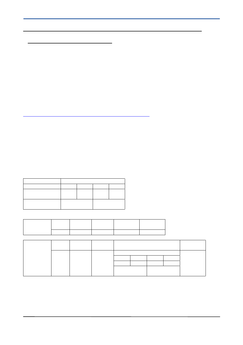
The following illustration shows the storage of a float value in the IEE-754 format and the order of
transmission in Modbus protocol on a typical example.
The mass flow value in user unit (holding register 528/529 decimal or 210/211 hex) should be read using
Modbus command 3:
Storage in registers:
Float value
44.996628
Byte number
Byte 3 Byte 2 Byte 1 Byte 0
Values in hex in
IEEE-754 notation
42
33
FC
8C
Register no.
529 dec.
(211 hex)
528 dec.
(210 hex)
Transmission via Modbus (all values in hex):
Request
from
host
Device
address
Modbus
command
Start
address
Number of
registers
Checksum
01
03
02 10
00 02
C4 76
Response
from
ROTAMASS
Device
address
Modbus
command
Number
of bytes
Data
Checksum
01
03
04
44.996628
7B 3D
Byte 1
Byte 0
Byte 3
Byte 2
FC
8C
42
33
Reg. 528 dec.
(Reg. 210 hex)
Reg. 529 dec.
(Reg. 211 hex)
Because of the order of transmission the registers eventually need to be swapped to get the float value in
the standard IEEE-754 format. Commercially available software might do this automatically. However, those
users who intend to write their own communication software must be aware of the order of transmission when
reading multiple registers and swap registers and/or bytes if necessary!