A1-8 – Yokogawa RAKD User Manual
Page 70
A1-8
IM 01R01B30-00E-E 5th edition February 01, 2013 -00
All Rights Reserved. Copyright © 2003, Rota Yokogawa
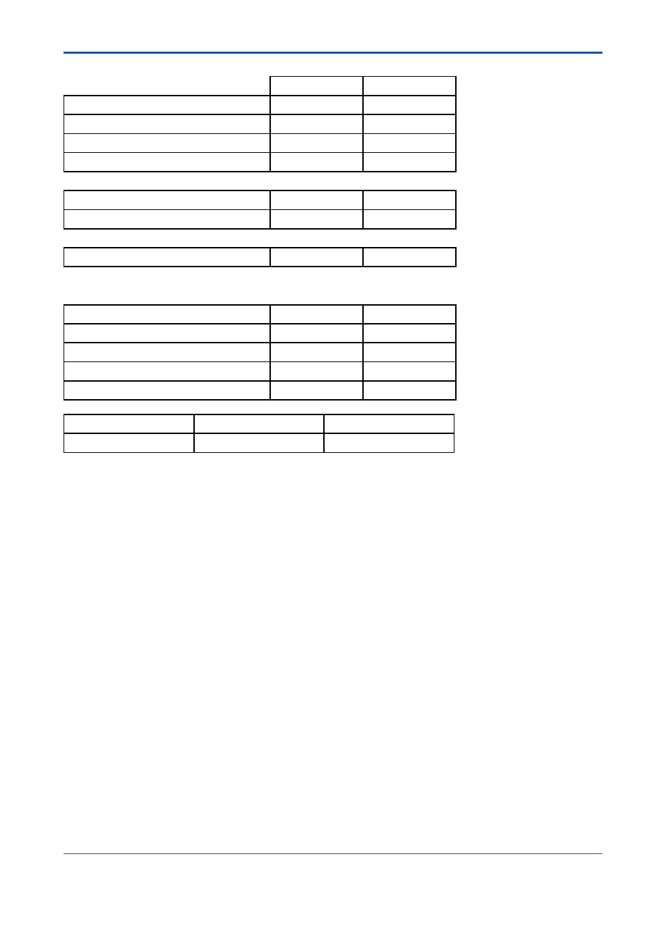
Table 7: Summary for RAKD ([V3]) with standard limit switches 7 – Failure rate
Profile 2
Profile 4
Fail Safe Detected (λSD)
0 FIT
0 FIT
Fail Safe Undetected (λSU)
262 FIT
367 FIT
Fail Dangerous Detected (λDD)
4 FIT
19 FIT
Fail Dangerous Undetected (λDU)
203 FIT
295 FIT
SFF
4
56.7%
56.7%
MTBF
226 years
153 years
SIL AC
5
SIL1
SIL1
Safety metrics according to ISO 13849-1
6
:
MTTF
d
(years)
551
364
DC
2%
6%
Category (CAT)
CAT 1
CAT 1
Performance Level (required)
PL
r
= c
PL
r
= c
Performance Level (calculated)
2.07E-07 1/h
3.14E-07 1/h
T[Proof] = 1 year
T[Proof] = 5 years
T[Proof] = 10 years
PFDAVG = 9.69E-04
PFDAVG = 4.49E-03
PFDAVG = 8.89E-03
3 The switching contact output is connected to a fail-safe NAMUR amplifier (e.g. Pepperl+Fuchs KF**-
SH-Ex1). The failure rates of the amplifier are not included in the listed failure rates
4 The complete sensor subsystem will need to be evaluated to determine the overall Safe Failure
Fraction. The number listed is for reference only.
5 SIL AC (architectural constraints) means that the calculated values are within the range for hardware
architectural constraints for the corresponding SIL but does not imply all related IEC 61508 requirements
are fulfilled.
6 Depending on the application and possible external diagnostics a higher DC
D
and therefore also a
higher category might be possible to achieve.
7 The switching contact output is connected to a standard switching amplifier (e.g. Pepperl+Fuchs KF**-
SR2-Ex*.W). The failure rates of the amplifier are not included in the listed failure rates.