Hazardous area specifications, Controller (option /r1 and r3), Metrological regulation in cis (gost) – Yokogawa RAKD User Manual
Page 38: Rakd “non incendive” (option /kn1)
IM 01R01B30-00E-E 5th edition January 01, 2013 -00
<7. TECHNICAL DATA>
7-8
All Rights Reserved. Copyright © 2003, Rota Yokogawa
HAZARDOUS AREA SPECIFICATIONS
RAKD with ATEX- certification “intrinsic safe”
(option /KS1)
Certificate :
KEMA 00ATEX 1037X
Output signal :
4–20 mA / Pulse output / Limit switches
Explosion proof :
Ex ia IIC T6 ... T4 Gb
Entity parameter :
Table 7-6
Analog
output
Pulse
output
Limit
switch
type 2
/K1-/K3
Limit
switch
type 3
/K1-/K3
Limit
switch
type 2
/K6-/K8
Limit
switch
type 3
/K6-/K8
Ui [V]
30
16
16
16
16
16
Ii[ mA]
100
20
25
52
25
52
Pi [mW]
750
64
64
169
64
169
Li [mH]
0.73
0
0.15
0.15
0.1
0.1
Ci [nF]
2.4
0
150
150
30
30
Temperature specification :
Table 7-7
Configura-
tion
Max.
ambient
temperature
Max.
process tem-
perature
Temperature
class
Transmitter
4-20mA /
Pulse
65°C
65°C
T6
50°C
80°C
45°C
100°C
T5
38°C
135°C
T4
Limit
switch(es)
type 2
65°C
65°C
T6
80°C
80°C
T5
59°C
100°C
100°C
100°C
T4
73°C
135°C
Limit
switch(es)
type 3
24°C
65°C
T6
37°C
80°C
T5
34°C
100°C
57°C
80°C
T4
54°C
100°C
48°C
135°C
For the configuration where a transmitter is combined with
limit switches, the temperature class is determined by the
most restrictive combinations of maximum ambient temperature
and maximum process temperature.
Description of limit switch type 2 and 3 see ATEX certificates
from Pepperl & Fuchs:
- PTB 99 ATEX 2219X ( SC2-NO) for /K1 to /K3
- PTB 00 ATEX 2049X (SJ2-S.N) for /K6 to /K10
RAKD “non incendive” (option /KN1)
Type “n” (non incendive) acc. EN 60079-15.
Explosion proof :
Ex nL IIC T6 protection „nL”; group II ; category 3G
Dust proof :
Ex II 3D; group II ; category 3D
Max. surface temperature : 80°C
Entity parameter :
see table 7-6
Temperature specification :
see table 7-7
CONTROLLER (Option /R1 and R3)
Differential pressure controller for a constant flow at
fluctuations of the process pressure.
These are no valves to reduce the pressure.
-
Controller /R1 for liquids with variable inlet or
outlet pressure and for gases with variable inlet pressure
and constant back pressure.
-
Controller /R3 for gases with fluctuations of the back pressure.
Max. liquid flow
: 100 l/h
Max. gas flow
: 3250 l/h
Max. pressure
: 25 bar
Recommended differential pressure
: >400 mbar
Temperature range : -25°C to + 80°C
Materials :
Table 7-5
Housing
Diaphragm
Springs
/R1 / /R3
CrNi-Steel
PTFE
CrNi-Steel
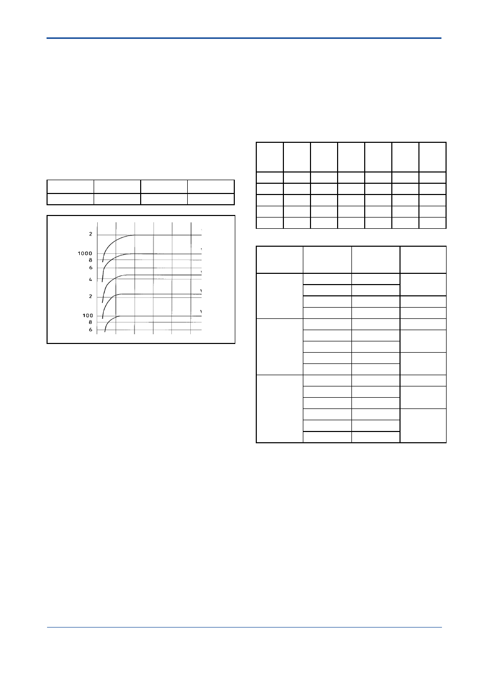
F2.EPS
l/h air at 20°C ; 1.013 bar abs.
Inlet pressure
Fig. 7-1 Diagram controller characteristic
COMPLIANCE WITH IEC 61508
RAKD with local indicator and standard or fail safe limit
switches (RAKD[][]-[][]SS-[][][][][]-T[][]NNN/K1…K10):
Suitable for application in safety functions up to and including
SIL2.
RAKD with valve and controller with local indicator and
standard or fail safe limit switches
(RAKD[][]-[][]SS-[][]V[][]-T[][]NNN/R[]/K1…K10):
Suitable for application in safety functions up to and including
SIL1.
Reliability data available on request in FMEDA report.
COMPLIANCE WITH ISO 13849
For Safety Metrics acc. to ISO 13849-2 please refer to the
FMEDA report.
METROLOGICAL REGULATION IN CIS (GOST)
RAKD has “Pattern Approval Certificate of Measuring
Instruments” and is registered as a measuring instrument in
Russia, Kazakhstan, Uzbekistan, Belarus and Ukraine.
The calibration laboratory of Rota Yokogawa is approved by
Federal Agency on Technical Regulating and Metrology in
Russia and other Metrological Organizations in CIS countries
to issue primary calibration confirmations for RAKD, option
/QR[].
Furthermore RAKD is RTN (GGTN) approved for installation
in hazardous areas.
For export to CIS countries please contact your Yokogawa
representative.