A1-5 – Yokogawa RAGN User Manual
Page 45
A1-5
IM 01R01B10-00E-E 2nd edition: November 01, 2011-00
All Rights Reserved. Copyright © 2011, Rota Yokogawa
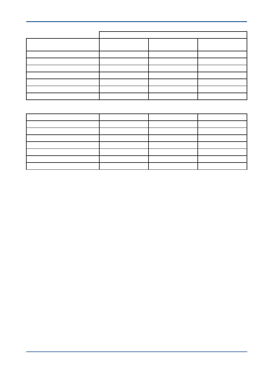
Table 2: Summary for RAGN – Failure rates
exida Profile 2
Version
[V1]
Reed contacts
[V2]
Fail-safe state LOW
[V3]
Fail-safe state HIGH
Fail Safe Detected (lSD)
0 FIT
0 FIT
0 FIT
Fail Safe Undetected (lSU)
20 FIT
2 FIT
11 FIT
Fail Dangerous Detected (lDD)
0 FIT
11 FIT
11 FIT
Fail Dangerous Undetected (lDU)
87 FIT
139 FIT
130 FIT
SFF
3
18%
8%
14%
MTBF
1035 years
738 years
738 years
SIL AC
4
SIL1
SIL1
SIL1
Safety metrics according to ISO 13849-1:
MTTFd (years)
1312
761
809
DC
5
0%
7%
8%
Category (CAT)
CAT 1
CAT 1
CAT 1
Performance Level (required)
PLr = c
PLr = c
PLr = c
Performance Level (calculated)
8.70E-08 1/h
1.50E-07 1/h
1.41E-07 1/h
PFDAVG, T[Proof] = 1 year
4.12E-04
6.61E-04
6.18E-04
PFDAVG, T[Proof] = 5 years
1.91E-03
3.06E-03
2.86E-03
PFDAVG, T[Proof] = 10 years
3.78E-03
6.07E-03
5.67E-03
3
The complete sensor subsystem will need to be evaluated to determine the overall Safe Failure Fraction.
The number listed is for reference only.
4
SIL AC (architectural constraints) means that the calculated values are within the range for hardware
architectural constraints for the corresponding SIL but does not imply all related IEC 61508 requirements
are fulfilled.
5
The switching contact output of [V2], [V3] is connected to a fail-safe NAMUR amplifier (e.g. Pepperl+Fuchs
KF**-SH-Ex1). The failure rates of the amplifier are not included in the listed failure rates