4 magnetic contact (option /gm1 to /gm5), 4 magnetic contact (option /gm1 to /gm5) -4, Connection to transmitter relay – Yokogawa RAGN User Manual
Page 18
<4. INSTALLATION
4-4
IM 01R01B10-00E-E 2nd edition: November 01, 2011-00
All Rights Reserved. Copyright © 2011, Rota Yokogawa
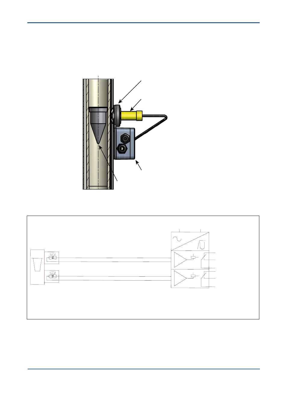
4.4 Magnetic contact (Option /GM1 to /GM5)
a) Loose the nut at the guide sleeve.
b) If 2 limit switches were ordered install the Max-contact in the top position and the Min- contact
in the low position (see print on housing).
c) Put the limit switch from the outer side on the guide rail of the Rotameter.
d) Adjust the distance between limit switch to tube to 1 mm; check function and correct if necessary.
e) Fix limit switch with the nut to guide rail.
Optional connection box /GD1
Limit switch /GM1 or /GM2
Float with magnet
Nut
F45.EPS
GRENZWERTSCHALTER GM
LIMIT SWITCH GM
CONTACT LIMITE GM
ROTAMETER RAGN with option /GMx (x = 1 ... 5)
EN 60947-5-6 (NAMUR)
MAINS / NETZ / TENSION
OPTION: /W4B 24VDC
KFD2-SR2-Ex.W
OPTION: /W2B 230VAC
KFA6-SR2-Ex.W
9
8
1
1
1
7
1
1
1
3
4
6
+
-
+
-
LIMIT/ GRENZWERT/ LIMITE
MAX
MIN
Ä
TRENNSCHALTVERST RKER
TRANSFORMER ISOLATED BARRIER
AMPLIFICATEUR SEPARATEUR
(L+
(L-)
EINKANALIGE VERSTÄRKER .......-SR2-EX1.W ANSCHLUSS WIE GRENZWERT "MAX"
ONE CHANNEL TRANSMITTER .....-SR2-EX1.W CONNECTION LIKE LIMIT "MAX"
UN CANAL AMPLIFICATEUR ........-SR2-EX1.W RACCORD COMME LIMITE "MAX"
LIMIT/ GRENZWERT/ LIMITE
Connection to transmitter relay :