Yokogawa RAGN User Manual
Page 36
<8. TECHNICAL DATA>
8-4
IM 01R01B10-00E-E 2nd edition: November 01, 2011-00
All Rights Reserved. Copyright © 2011, Rota Yokogawa
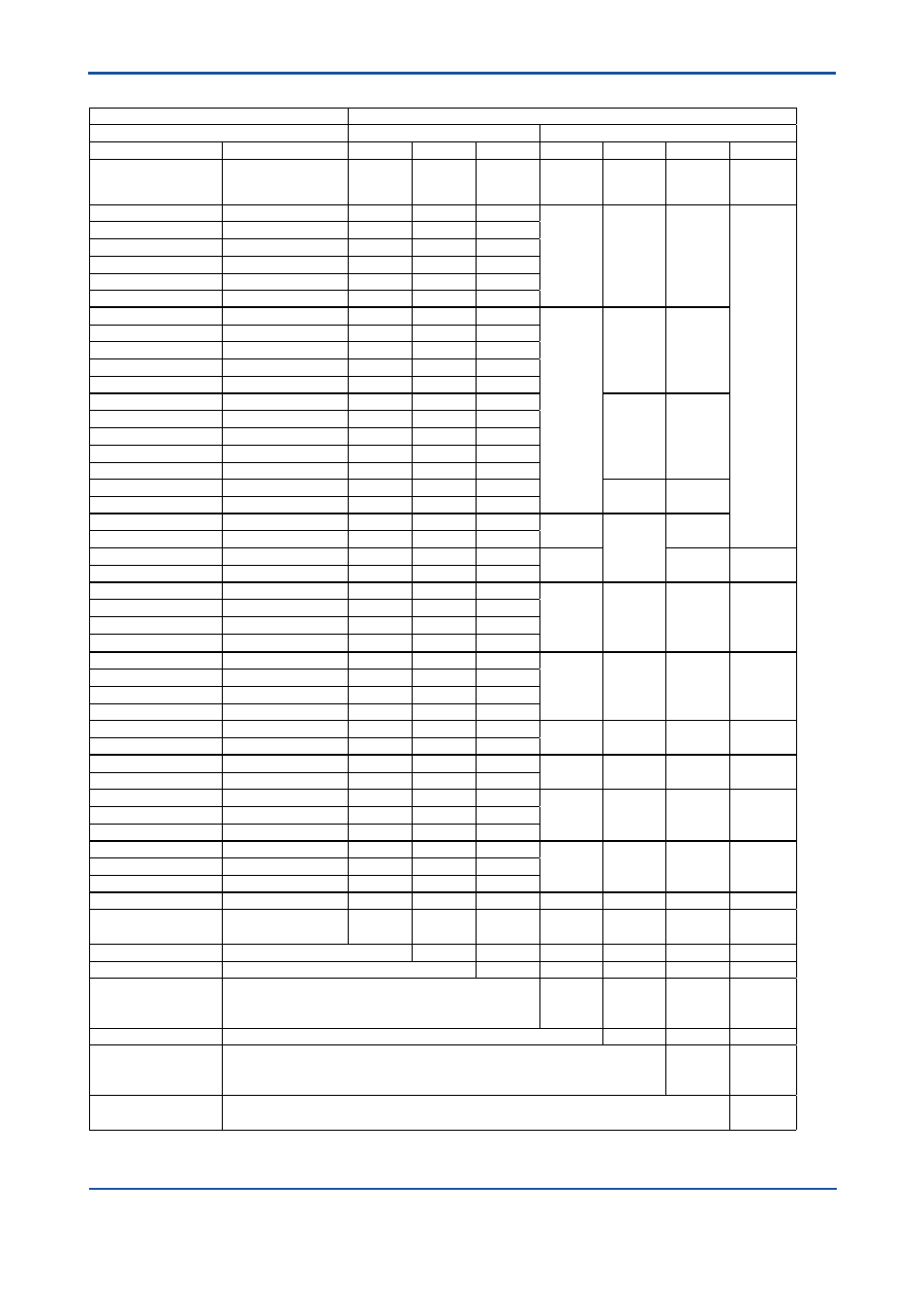
FLOW TABLE WITH METERING TUBE-FLOAT-COMBINATION FOR AIR / GASES
Flow table
Suffix code metering tube - float- combination
Air/Gases 20°C, 1 bar abs
Metering tube
Float
-x
x
xx
-xx
x
x
x
Max. Flow
[l/h]
Pressure loss
[mbar]
Length
Code
Diameter
Code
Cone
Code
Material
Code
Diameter
Code
Flow
mark
Code
Insertion
Code
1.9
1
L
6
13
TT
A
G
N
3
1
L
6
14
4.4
2
L
6
17
6.5
2
L
6
21
10
3
L
6
22
14
4
L
6
23
23
2
L
6
24
PD;TT
B
G
33
2
L
6
27
50
2
L
6
31
70
3
L
6
32
100
4
L
6
33
180
3
L
7
34
C
G
250
3
L
7
37
400
3
L
7
41
630
4
L
7
42
1000
5
L
7
43
1600
5
L
7
44
D
G
2400
10
L
7
47
1600
4
P
0
51
PF
0
6
2500
6
P
0
52
2400
8
P
0
51
PD
7
M
1)
3800
11
P
0
52
6000
6
P
1
53
PD
1
7
M
1)
9300
7
P
1
54
14500
8
P
1
57
23000
10
P
1
61
400
5
P
1
53
PF
1
6
N
6300
5
P
1
54
10000
6
P
1
57
16000
8
P
1
61
35000
11
P
2
62
PD
2
7
M
1)
55000
13
P
2
63
25000
8
P
2
62
PF
2
6
N
40000
10
P
2
63
88000
29
P
4
64
PD
4
7
M
1)
140000
32
P
4
67
220000
34
P
4
71
63000
13
P
4
64
PF
4
6
N
100000
14
P
4
67
160000
17
P
4
71
Description
Length metering tube
300 mm .....................
300 mm .....................
P
L
Diam. metering tube
10 mm to 81 mm ..........................
x
Cone metering tube
See flow table ..................................................
xx
Float material
Titanium ...............................................................................
PTFE ....................................................................................
PVDF ...................................................................................
TT
PF
PD
Float diameter
1.6 mm to 54 mm ....................................................................................
x
Flow mark
For gas .......................................................................................................................
For air ..........................................................................................................................
For air ..........................................................................................................................
G
6
7
Float insertion
Without magnet ..............................................................................................................................
With magnet ...................................................................................................................................
N
M
1)
1)
For option limit switch /GM1 to /GM5