Yokogawa RAGN User Manual
Page 17
<4. INSTALLATION>
4-3
IM 01R01B10-00E-E 2nd edition: November 01, 2011-00
All Rights Reserved. Copyright © 2011, Rota Yokogawa
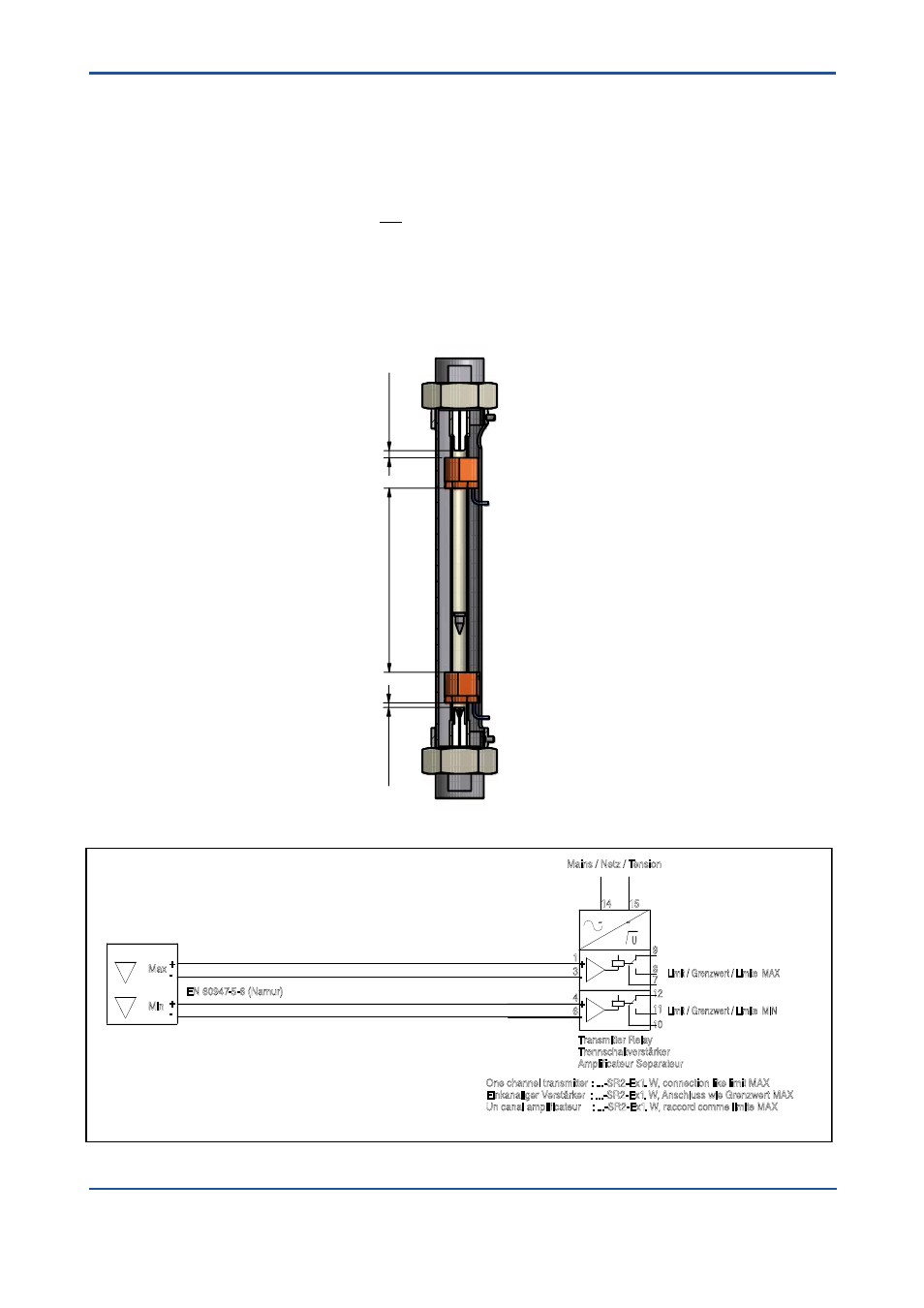
4.3 Bistable inductive ring sensor (Option /GR2 to /GR8)
- The ring sensor should be connected to a mono stable transmitter relay.
- Connection to transmitter relay (s. installation diagram below)
white cable
→
+
shielding
→
–
- The installation regulations in accordance with IEC 364 have to be taken into account.
- The shielding of the connection cable is not for earthing of the ring sensor. A ring sensor with a damaged
cable insulation may not be used
- The device has to be protected from strong electromagnetic fields.
- Power lines have to be installed separated from the signal lines.
- Switches, power relays and engines can change the switching state of the ring sensor (in unfavorable orders).
- Metal parts should have a minimum distance of 50 mm to the ring sensor.
- If the float is above the ring sensor after power on or after power fail, the float has to move once through
the ring sensor to find the correct float position.
15
4
6
3
1
14
12
10
11
8
7
9
U
Mains / Netz / Tension
One channel transmitter : ...-SR2-Ex1. W, connection like limit MAX
Einkanaliger Verstärker : ...-SR2-Ex1. W, Anschluss wie Grenzwert MAX
Un canal amplificateur : ...-SR2-Ex1. W, raccord comme limite MAX
Transmitter Relay
Trennschaltverstärker
Amplificateur Separateur
Limit / Grenzwert / Limite MIN
Limit / Grenzwert / Limite MAX
Max
Min
EN 60947-5-6 (Namur)
-
+
-
+
~
~
+
-
+
-
Option /W4B 24VDC
KFD2-SR2-Ex2.W
Option /W2B 230VAC
KFA6-SR2-Ex2.W
Inductive ring sensor
Induktiver Ringinitiator
Bague inductive
Rotameter
RAGN
option
/GRx (x = 2 ... 8)
F41.EPS
Connection to transmitter relay :
For installation in hazardous area see chapter 6 "EXPLOSION PROTECTED TYPE INSTRUMENTS”.
min.
6 mm
min.
4 mm
min.
25 mm